
How to build a Simple Solar Powered Automatic Garden Light
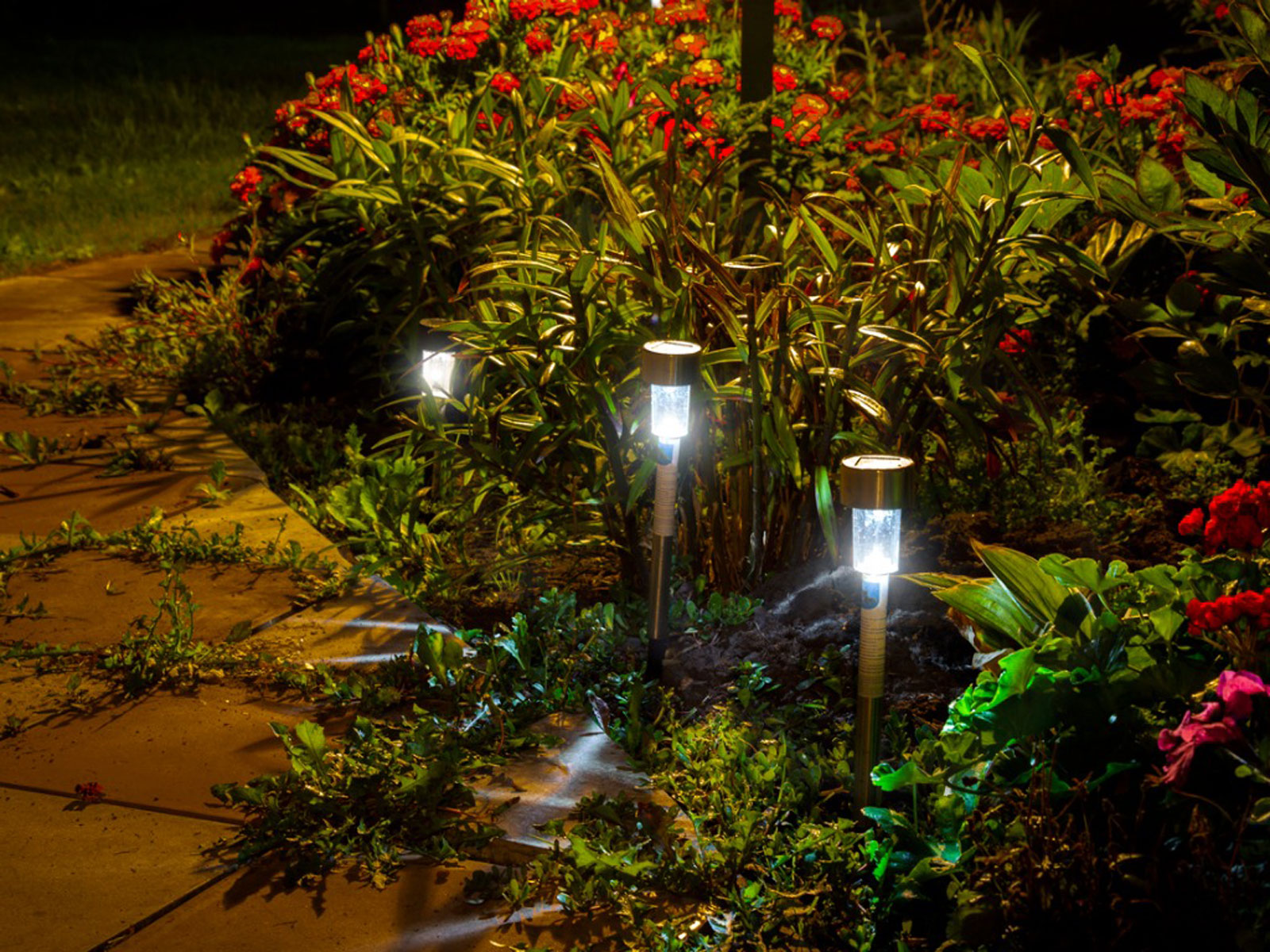
Those who have a strong interest in gardening can enjoy the beauty of their plants even at night thanks to a garden light. It’s not a good idea to run wires through your garden soil, which will be wet and tended to most of the time, so these lights are usually placed in the garden away from electrical outlets. Fortunately, there are solar-powered garden lights that can help with this problem.
Solar panels in the daylight charge the lights’ battery, which is then used to power them at night, reversing the process until it is fully charged. Solar-powered cell phone charger and inverter circuit have both been the subject of some of our previous articles.
We’re going to build a simple and inexpensive DIY solar garden light in this tutorial. During the day, a lithium battery is charged by the solar panel, and at night, the battery powers the lights until the sun comes out again. We will not use a microcontroller or sensor in this circuit because the goal is to reduce the number of components and thus the circuit’s cost and complexity. We can begin building our own solar light now, shall we?
Solar Garden Light Design
Our project’s load must be determined before we can begin selecting components and drawing a circuit diagram. When we talk about the “load,” we’re referring to the specific kind of Garden Light we’ll be using for this project. Because the circuit’s design is dictated by the light’s voltage and current rating.
Normal Chinese LEDs with an operating voltage of 3.2V and maximum forward voltage of 4.5V are used in this project’s LEDs. As a result, a series connection of two LEDs yields a forward voltage of 6.4V. We’ve included images of the LEDs we used in our project here.

If you have a 7.4V lithium battery, you can get from 6.4V to 8.4V out of it (fully charged). As a result, this project uses a 7.4V Lithium battery as a power source. If you’re not familiar with lithium batteries, this article on the fundamentals of lithium-ion batteries can help.
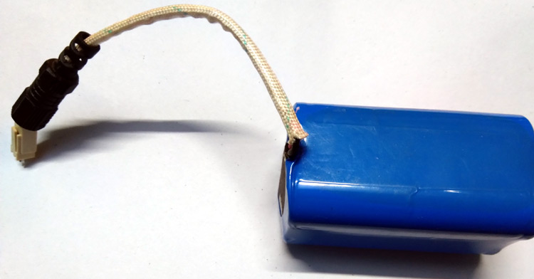
An inbuilt protection circuit will be included in the battery that is selected for this application to prevent overcharge, deep discharge and short circuits. Lithium batteries can become extremely unstable and even explode if not handled properly, so if your battery doesn’t have these safety features, be sure to use an external protection module.
Solar Garden Light Circuit Diagram
Parts of the solar garden light circuit are as follows: There are two functions: charging and controlling the LEDs. There are two parts to the explanation of the entire circuit diagram.
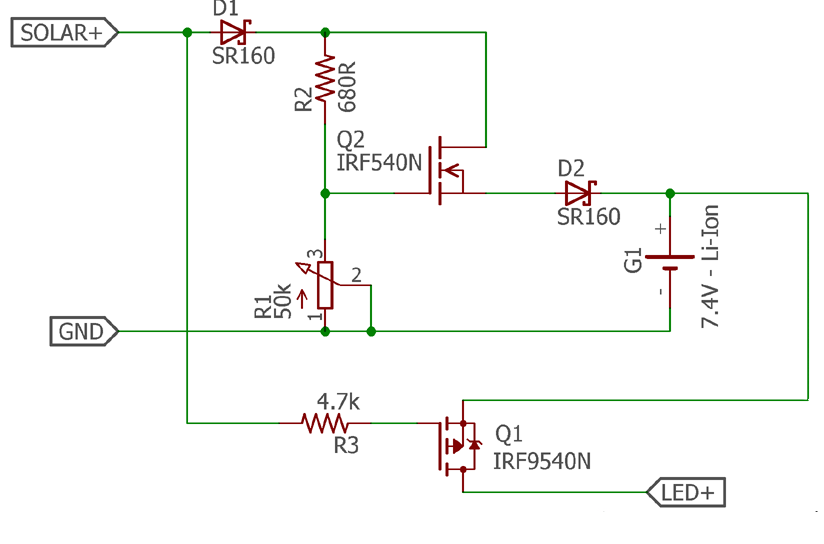
N-Channel MOSFET Q2, IRF540N, is used to control the charge. The gate voltage across N Channel MOSFET Q2 is controlled by potentiometer R1 to set the battery voltage level. Reverse polarity protection and reverse flow blocking are two functions of the Schottky rectifier diode D1, which is an SR160, a 1A 60V Schottky diode. It’s possible to isolate the charger voltage from the battery voltage by means of the output Schottky diode D2.
The other part of the circuit is responsible for turning on the LED when it is dark. The IRF9540 P-Channel MOSFET serves this purpose. The solar voltage regulates the MOSFET gate. As a result, the MOSFET is always off when the solar cells are generating voltage, but when the cells are not generating voltage, the MOSFET is always on. Additional LDR and comparator circuits can be completely eliminated by utilising P Channel MOSFETs.
The LEDs are now connected in series and parallel for the remainder of the circuit. However, the current flowing through LEDs becomes divided when two are connected in series. Two LEDs are connected in series to form four parallel connections. Paralleling more LEDs increases the current and reduces battery life.
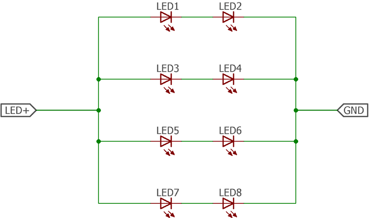
Each series is thought to be carrying about 40 milliamperes of current. Consequently, 160mA of current is required to power four parallel strings. When the battery is fully charged, the LEDs can be illuminated for nearly six hours at a time. It is possible to add more LED strings if necessary.
Solar Garden Light Construction & Hardware Required
- Lithium battery 7.4V (mAH depends on the backup time) with an inbuilt protection circuit.
- LEDs with 3.5V forward voltage (Another voltage is also applicable but the LED strip construction will be different)
- IRF9540N – P channel Mosfet
- IRF540N – N Channel Mosfet
- SR160 Schottky diode 2 pcs
- 680R resistor
- 50k potentiometer
- 4.7k resistor
- Solar Panel 15 – 18V with more than 300mA current rating if a 3600mAH battery is selected.
- Wires for connecting solar panel and LEDs
- Hookup wires
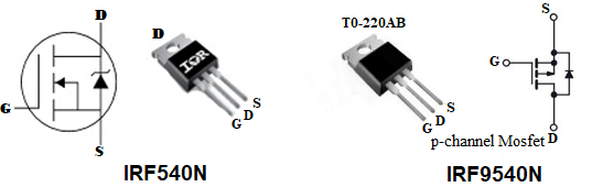
The below image shows the pinout of IRF540N N-channel and IRF9540 P-Channel Mosfet, that we will be using the project.
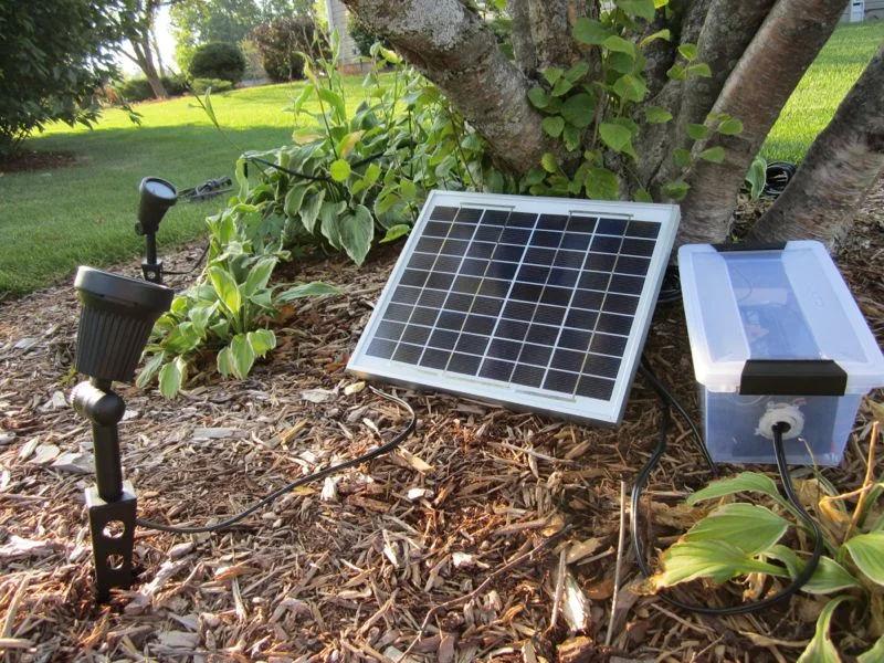
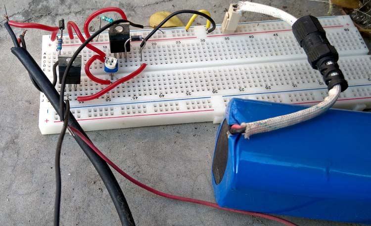
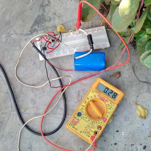
Once the Solar garden light circuit is constructed on a breadboard, my arrangement looks like this below
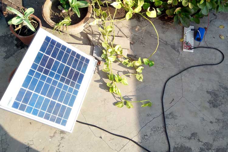
We have used the solar panel with the below specification.

It is a 10W solar panel with an output voltage of 18V. ‘ At the height of the solar cycle, the solar panel is positioned in direct sunlight. The potentiometer is set to 8.5 volts across D2 at all times. Lithium batteries have a maximum charging voltage of 8.4 volts when fully charged. In order to monitor the charging current, an amp meter is connected in series with the battery. A solar tracker can also be used to maximize battery charging, but this project does not cover that option.
The charge current can be seen on the multimeter reading below, which is nearly 300mA. On sunny days, this change will be more pronounced, while on cloudy days, it will be less pronounced.
This means that at night, when the solar panel is not receiving any sunlight, the battery will not be charged, which will result in LED lights turning on. To see how this works in action, click here to watch a video that shows the light turning on automatically when there is no light coming from the panel.
Further Improvements
The circuit is a simple lithium battery charger for a garden light project. Thus, there are no safety concerns. Dedicated driver ICs can be used for proper charging and employing proper solar charge methods using MPPT (Maximum Power Point Tracker).
An enclosed box and proper PCB are required for this outdoor operation project. The Enclosure must be constructed so that the circuit is watertight in the event of rainfall. The Circuit Digest’s active forum is the best place to discuss modifications to this circuit or other aspects of this project.
Conclusion
I hope all of you have understood How to build a Simple Solar Powered Automatic Garden Light. We MATHA ELECTRONICS will be back soon with more informative blogs soon.