
ESP32 Timers & Timer Interrupts
If something needs to happen at a specific time, timers and timer interrupts are the tools you need. Using a timer is akin to interrupting someone. It functions like a simple clock, measuring and controlling events in time while imposing a precise delay.

Almost all microcontrollers have built-in timers, which can be used for both time delays and as a countdown clock. The timer’s ability to be used in a variety of ways is a useful feature. Dedicated function registers are used to control the timers in the microcontroller.
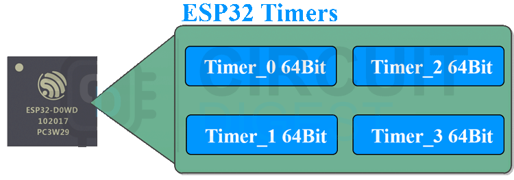
In the ESP32 chip, there are two hardware timers. Two general-purpose hardware timers are available to each group. They are all auto-reloadable 64-bit generic timers built on 16-bit prescales and 64-bit up/down counters.
Timer Interrupts
An LED can be reliably supplied with a pulse by using a Timer Interrupt to ensure timed events occur to the millisecond. This allows for fine-tuned clock or PWM operations. It is the software interrupts generated by the timer that is referred to as timer interrupts.
If you want to perform a task at a specific time interval, you can use timer interrupts to do so. Timer-based interrupts are similar to external interrupts in that they are triggered by an internal event rather than an external event.
As soon as the current instruction completes, they interrupt the thread of execution and call the interrupt handler (ISR), and they return to the next instruction from where they left off when the interrupt is complete. Here’s a visual representation of how the Timer works.
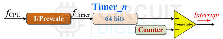
Because these timers are hardware-based, all timing is based on the timer’s own clock. Using the following formula, you can determine the timer’s speed:
timer speed (Hz) = Timer clock speed (Mhz) / Prescaler
There are two prescaler values that can be used to determine the Prescaler value of the timer in an ESP32: one that is equal to the clock frequency, and the other that is equal to the Prescaler value multiplied by 80.
It is the Prescaler that is used to divide the above frequency into a “tick” for the timer (increment its counter). After a certain number of ticks, the ISR is configured to fire. The process flow with a timer interrupt is shown in the image below.
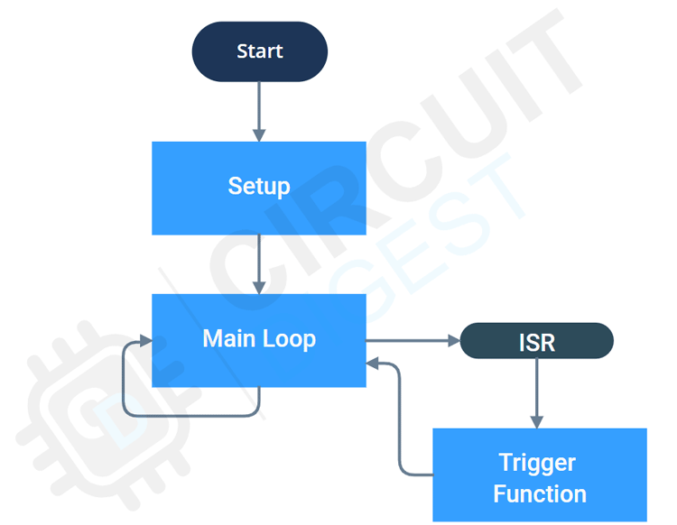
The best way to run non-blocking functions at regular intervals is to use timer interrupts, which are similar to hardware interrupts in that respect. In the setup function, we will configure and attach a specific interrupt to a specific ISR. There will be no interruptions in the controller’s main loop execution.
As soon as the microcontroller receives a timer interrupt, it suspends the main loop and begins executing the Interrupt Service Routine (ISR). The microcontroller will resume the main loop from where it was paused once the ISR is complete. Each Timer Interrupt will result in a new iteration of this process.
ESP32 Timer Interrupt Example – Blinking an LED
A blinking LED program is the focus of this demonstration. In this case, we’ll use timer interrupts instead of delays. Make the breadboard connections as shown in the circuit diagram below.

As shown in the schematic, here is the completed circuit mounted on a breadboard.
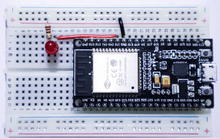
It is recommended that you use a 220 Ohms resistor in place of the LED’s cathode connection to GND.
ESP32 Code to Blink an LED with Timer Interrupt
Upload the ESP32 code found at the bottom of this article by downloading it. 1Hz blinking is clearly visible on the LED. Let’s break down the code piece by piece.
| #define LED 21 hw_timer_t *My_timer = NULL; |
The LED pin is designated GPIO21 in the global variable area. In order to set up the timer, we created a pointer variable named My timer of type hw timer t.
| #define LED 21 hw_timer_t *My_timer = NULL; |
Then we created the interrupt handler for the timer interrupt. GPIO21’s state is reversed in the ISR function we wrote. When the timer interrupts, this ISR is called.
| void setup() { pinMode(LED, OUTPUT) My_timer = timerBegin(0, 80, true); timerAttachInterrupt(My_timer, &onTimer, true); timerAlarmWrite(My_timer, 1000000, true); timerAlarmEnable(My_timer); } void loop() { } |
And in the Setup function, we used the pinMode macro to initialize GPIO21 as an output.
| My_timer = timerBegin(0, 80, true); |
We are using the timerbegin function with the following parameters to start the timer. As there are four hardware clocks in total, we can set the timer’s number from 0 to 3. The prescaler’s value and a true/false flag determine whether the counter should count up or down (false). To count up, we’ll use timer 0 in conjunction with prescaler 80 and a counter.
| timerAttachInterrupt(My_timer, &onTimer, true); |
First, we need to hook up the timer to an interrupt service routine (ISR), which will be called whenever an interrupt is received. The timerAttachInterrupt function is used to accomplish this. The onTimer ISR function has been attached to the timer interrupt in this example.
| timerAlarmWrite(My_timer, 1000000, true); |
The counter value in which the timer interrupt should be generated is specified using the timerAlarmWrite function. Because we want to generate an interrupt once every second in this example, we pass a value of 1000000 microseconds. We’ll use the value true for the third argument, so the counter will reload and the interrupt will be generated on a regular basis.
| timerAlarmEnable(My_timer); |
At last, we are enabling the timer interrupt using the function timerAlarmEnable.
Code
| #define LED 21 hw_timer_t *My_timer = NULL; void IRAM_ATTR onTimer(){ digitalWrite(LED, !digitalRead(LED)); } void setup() { pinMode(LED, OUTPUT); My_timer = timerBegin(0, 80, true); timerAttachInterrupt(My_timer, &onTimer, true); timerAlarmWrite(My_timer, 1000000, true); timerAlarmEnable(My_timer); //Just Enable } void loop() { } |
Conclusion
I hope all of you have understood the basics of ESP32 Timers & Timer Interrupts. We MATHA ELECTRONICS will be back soon with more informative blogs soon.