
How to Build a High Efficiency Class-D Audio Amplifier using MOSFETs
Digital media consumption has changed dramatically over the past few decades, from a simple tube amp to today’s high-tech media players. Because of their vibrant sound quality and long battery life, portable media players have become one of the first choices for consumers among these innovations.
So tell me how it works and how it manages to sound so great. As a techie, this question is always at the top of my to-do list. In spite of advances in speaker technology, the obvious answer to this question is a Class D amplifier, which is a digital amplifier.
As a result, we’ll use this project to examine the advantages and disadvantages of a Class D amplifier. Finally, a hardware prototype amplifier will be constructed and its performance will be evaluated. It’s intriguing, isn’t it? So, without further ado, here we go.
What is a Class-D audio amplifier?
Switching amplifiers are the simplest answer. However, in order to understand how it works and how the switching signal is generated, you can refer to the block diagram provided in the following section.
So why a switching amplifier?
Class D audio amplifiers have a higher efficiency than Class A, Class B, and Class AB amplifiers. Because Class AB amplifiers operate in the active region and suffer from low power loss, it is possible to calculate their maximum efficiency by multiplying the collector-emitter voltage by the current. Here, we’ve covered all of the relevant loss factors in our article on the various classes of power amplifiers.
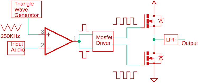
In our simplified block diagram of the Class D audio amplifier, you can see that at the non-inverting terminal, we have our audio input, and on the inverting terminal, we have our high-frequency triangular signal.. The comparator’s output is high when the input audio signal voltage exceeds the voltage of the triangular wave, and it is low when the input signal voltage is low. Basically, we used a MOSFET gate drive IC to drive the gates of two MOSFETs, one on the high side and one on the low side, by modulating the input audio with a high-frequency carrier signal. In order to obtain our final audio signal, we must first pass the high-frequency square wave output through a low-pass filter stage.
Components Required to build Class-D Audio Amplifier Circuit
Now that we’ve learned the basics of a Class-D audio amplifier, we can begin searching for the components we need to build our own. As this is a simple test project, most of the components can be purchased at a local hobby shop. You can see the components and their images below.
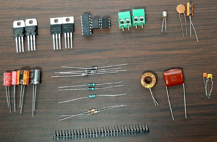
Components Required:
- IR2110 IC – 1
- Lm358 OP-Amp – 1
- NE555 Timer IC – 1
- LM7812 IC – 1
- LM7805 IC – 1
- 102 pF Capacitor – 1
- 103 pF Capacitor – 1
- 104 pF Capacitor – 2
- 105 pF Capacitor – 1
- 224 pF Capacitor – 1
- 22uF Capacitor – 1
- 470uF Capacitor – 1
- 220uF Capacitor – 1
- 100uF Capacitor – 2
- 2.2K Resistor – 1
- 10 K Resistor – 2
- 10R Resistor – 2
- 3.5 mm Audio Jack – 1
- 5.08 mm Screw Terminal – 2
- UF4007 Diode – 3
- IRF640 MOSFETs – 2
- 10K Trim POT – 1
- 26uH Inductor – 1
- 3.5 mm Headphone Jack – 1
Class D Audio Amplifier- Schematic Diagram
The schematic diagram for our Class-D amplifier circuit is shown below:

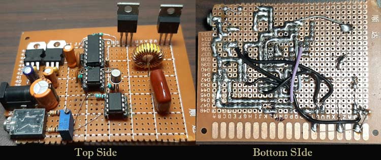
Building the Circuit on PerfBoard
We built the circuit on a piece of perfboard, as shown in the main image. Firstly, the circuit is very simple, and secondly, we can easily modify it if something goes wrong. In the final stages, we had to use some hookup wires to complete the build with the help of copper wire. Above, you can see the finished perfboard circuit.
Working of Class-D Audio Amplifier
In this section, we’ll go over each of the circuit’s major blocks and explain them in detail. You can pick up all the parts for this Class-D audio amplifier at your local hobby store because it is based on an Op-amp.
- The Input Voltage Regulators:
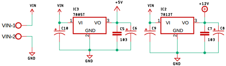
To begin, we use voltage regulators such as the LM7805 (5 volts) and the LM7812 (12 volts) to regulate the input voltage. For the purpose of powering the circuit, a 13.5V DC adapter is needed, but to power the NE555 and IR2110, 5V and 12V power supplies are also required. This is important.
- Triangular Wave Generator with 555 Astable Multivibrator:
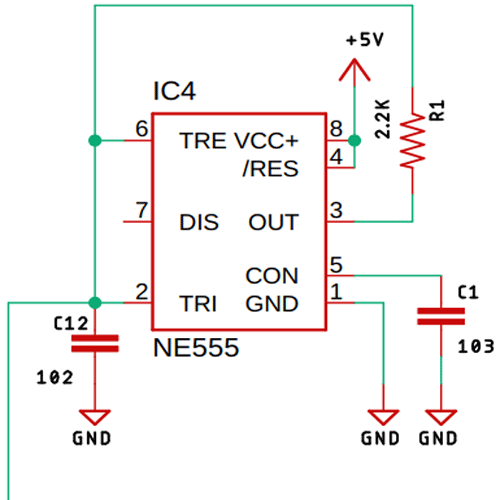
To generate a 260KHz triangular signal, we used a 555 timer and a 2.2K resistor. If you’re interested in learning more about the Astable Multivibrator, check out our previous post on the 555 Timer Based Astable Multivibrator Circuit, in which we described all the calculations.
- The Modulation Circuit:
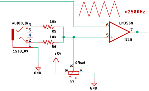
The input audio signal was modulated using a simple LM358 Op-Amp, as shown in the image above. In terms of incoming audio signals, we’ve used two 10K input resistors and a potentiometer to offset the zero signal present in the input audio. We’re only using one power supply. When the input audio signal exceeds the input triangular wave, the comparator’s output will be high, resulting in a modulated square wave that can be fed to a MOSFET gate driver IC.
- The IR2110 MOSFET Gate Driver IC:
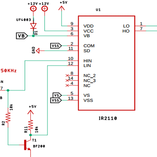
A MOSFET gate driver IC was used to drive the MOSFET properly because we are working at some moderately high frequencies. Circuitry is arranged in accordance with the IR2110 IC’s datasheet. A high-frequency transistor, the BF200, was used to generate the inverted square wave of the input signal because this IC requires an inverted signal for proper operation.
- The MOSFET Output Stage:
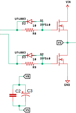
There are always transients when working with high frequency and inductors, which is why flyback diodes like the UF4007 are used as flyback protection for the MOSFET output stage, as you can see in the image above.
- The LC Low-Pass Filter:
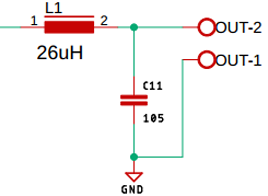
High-frequency square waves are generated by the MOSFET driver stage and are not suitable for driving loads such as loudspeakers. The C11 low pass filter uses a 26uH inductor and a 1uF non-polarized capacitor to guard against this. Here’s how a basic circuit works.
Testing the Class-D Amplifier Circuit
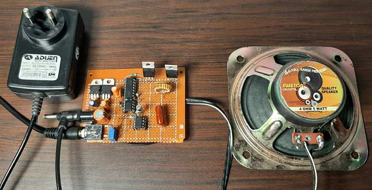
The circuit is powered by a 12V power adapter, as shown in the image above. Using an inexpensive Chinese one, I get 13.5V out of it, which is perfect for our on-board LM7812 voltage regulator because it’s a little bit more than 12V. I’m using a 4 ohm, 5 watt speaker as a load. My laptop has a long 3.5mm audio jack, so I’m using that for the audio input.
There is no noticeable humming sound when the circuit is powered on, but as you can see in the video, this circuit is not perfect and it has a clipping issue at higher input levels, so this circuit has much room for improvement. Because the MOSFETs remained cool under moderate loads, no heat sink was required for these tests.
Further Enhancements
Despite its simplicity, this Class D power amplifier circuit still needs work. The sampling technique was the most problematic aspect for me, and I believe it can be improved. A perfect low pass filter stage necessitates accurate calculations of inductance and capacitance in order to reduce amplifier clipping. For optimal performance, the circuit can be built on a PCB. In the event of overheating or a short circuit, a safety circuit can be added.
Conclusion
I hope all of you have understood How to Build a High-Efficiency Class-D Audio Amplifier using MOSFETs. We MATHA ELECTRONICS will be back soon with more informative blogs soon.