
How to Build a 18650 Lithium Battery Charger and Booster Module
Using the TP4056 Li-Ion Battery Charger IC and the FP6291 Boost Converter IC, we will build a single-cell Lithium battery charger and booster module in this tutorial. When using lithium batteries to power our electronic projects, a battery module like this will come in handy. For most of our development boards, the module can safely charge a lithium battery and boost its output voltage to a regulated 5V. Although the charging current of our module is set at 1A, it can be easily modified to provide up to 2.5A if necessary and supported by the battery, so long as it is compatible with the module.

All of this will be covered in detail in this tutorial, including how I came up with the circuit diagram, how the PCB was designed, and how I ordered it. To get a better idea of how this circuit works, please read the introduction to lithium batteries and Lithium battery charger circuit before you proceed.
For this project, we used PCBWay to procure the PCB boards. It has been explained in great detail in the following sections of this article how to design, procure and assemble the circuit’s PCB boards.
Components Required
- TP4056 Li-Ion Battery Charger IC
- FP6291 Boost Converter IC
- USB Type-A Female Connector
- Micro USB 2.0 B type 5 Pin Connector
- 5× Resistor (2×1k, 1.2k, 12k, 88k)
- 6× Capacitor (2×0.1µf, 2×10µf, 2×20µf)
- 2× LEDs
- 1× Inductor (4.7µH)
- 1× Diode (1N5388BRLG)
- 18650 Lithium cell
Circuit Diagram and Explanation

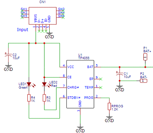
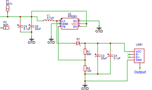
Above you’ll find a schematic diagram for the 18650 Lithium Battery Charger & Boost Module. The battery charging circuit and the DC to DC boost converter are the two main parts of this circuit. Battery voltage can be boosted from 3.7 volts to between 4.5 and 6 volts by using the Booster part. USB Type A Female Connector on the Booster side, and Micro USB 2.0 B type 5 Pin Connector on the Charger side were used in this circuit.
There is a dedicated lithium-ion battery charger in the circuit that is used to charge the battery The TP4056 is a single-cell Lithium-ion linear charger with a constant-current/constant-voltage output. Small external parts count and small SO package make the TP4056 ideal for portable applications. This IC processes the 5V DC input supplied through the Micro USB socket to charge the battery. The LEDs attached to it indicate the charging status.
In order to design the circuit, the FP6291 IC is used. In some applications, such as obtaining a steady 5V from a 3V battery, this 1 MHz DC-DC Step-Up Boost IC can be used. The battery terminals (+ and -) are used to supply power to the Boost Converter circuit, which is then processed by the FP6291 IC to provide a steady 5V DC supply via the standard USB socket at the output.
Fabricating PCB 18650 Lithium Battery Charger & Booster Module
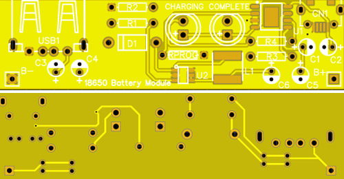
To build the PCB for our project, we must first learn how schematics work. Using any PCB design software of our choice, you can create the circuit board. When it’s all said and done, our PCB should look something like this.
The PCB layout for the above circuit is also available for download as Gerber from the link:
It’s time to get them made using the Gerber file now that our design is complete. It’s simple to finish the PCB; just follow the steps listed below:
Ordering PCB from PCBWay
Step 1: Get into https://www.pcbway.com/, sign up if this is your first time.
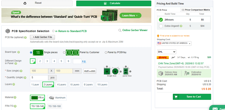
You’ll then need to enter the dimensions of your board, as well as how many layers and how many boards you’ll need.

Step 2: Click the “Quote Now” button to proceed. On the next page, you’ll be able to tweak the settings for things like the material and track spacing, if necessary. However, most of the time, the default values are sufficient.

Step 3: The final step is to upload the Gerber file and proceed with the payment. To make sure the process is smooth, PCBWAY verifies if your Gerber file is valid before proceeding with the payment. This way, you can sure that your PCB is fabrication friendly and will reach you as committed.
Assembling and Testing the 18650 chargers and Booster Module
After a few days, we received our PCB in a neat package and the PCB quality was good as always. The top layer and the bottom layer of the board is shown below.

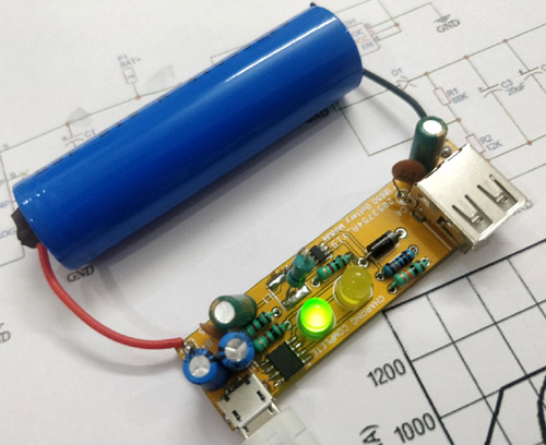
A red and black wire was soldered to each of the 18650 cell’s B+ and B- pins after assembling all of the components. In the absence of a spot welder, I used magnets to keep the 18650 batteries connected. Detailed images of the completed module and its accompanying lithium battery can be seen in the gallery below.

LEDs on the board show the module’s charging status. An illuminated yellow LED indicates that charging has been completed or the module is awaiting a charged battery, while a glowing green LED indicates charging is in progress. Unless a charger is plugged in, the green and yellow leds on the battery can be charged via the micro USB port. Make sure the output current of the charger is at least 1A when using this module. The green LED on the charging module can be seen in the image below.
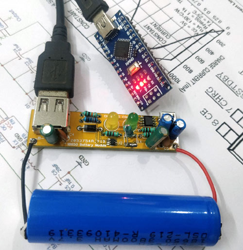
The USB port’s output voltage is 5V and 1A. To power electronic devices, the voltage of the 18650 cells is raised to 5 volts. The image below illustrates how the module can be used to power an Arduino nano.
Although the module’s maximum output current can theoretically be configured to 2.5A, I was only able to get 1.5A when the resistor was set to 2.5A. If this is happening, it’s possible that my battery or the boost IC is to blame. The low-cost boost circuit will work fine if the load current is less than 1 A.
Conclusion
I hope all of you have understood How to Build a 18650 Lithium Battery Charger and Booster Module. We MATHA ELECTRONICS will be back soon with more informative blogs soon.