
Digital Voltmeter using 8051 Microcontroller
The input voltage range for this project is 0 to 25 volts. To produce an accurate output on the LCD, the input voltage in this case needs to be DC voltage. You will see the continuously running figures on the LCD if you add AC voltage as the input because AC varies continuously.

The 8051 microcontrollers, a voltage sensor module, and an ADC IC ADC0804 are the project’s main building blocks. In this project, the voltage is shown using an analog to digital conversion procedure.
Analog to Digital Conversion
In the real world, analogue data predominates. Analog to digital conversion is required in order for a microprocessor or microcontroller to understand and work with the data when manipulating it using digital systems.

Interfacing of Physical Quantity to Digital System
- Transducer: A transducer, often known as a sensor, is a device that transforms a physical quantity into electrical energy. Examples of transducers include light-dependent resistors, temperature sensors, humidity sensors, gas sensors, etc.
- ADC (Analog to Digital Converter): ADC converts analog voltage to a digital value.
- Digital System: For understanding purposes, this system reads digital data input and shows the physical quantity on the LCD.
Based on the electrical input voltage, the ADC IC in this case generates the output digital value. This digital value is read by the 8051 microcontroller, which then displays it on the LCD.
- AT89C51 microcontroller
- ADC0804 IC
- 25V Voltage Sensor
- AT89C51 programming board
- Variable resistor (to demonstrate the program)
- DC Adapter or Battery
Digital Voltmeter Circuit Design using 8051 Microcontroller
The PORT2 in the circuit above is connected to the data bits of the analog to digital converter IC. The POTR3 of the controller is where the LCD data pins are linked, while P1.6 and P1.7 are where the control pins RS and EN are attached.

ADC0804
An 8-bit analog to digital converter is being used here. The successive approximation approach is used by this IC to translate analog values into digital. There is a maximum input of one analogue data. The reference voltage at pin 9 can be changed to alter the step size of this IC. If this pin is not connected, the reference voltage will be VCC.
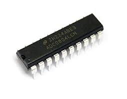
When the step size is set to 5V, the output is increased by 1 value for every 19.53mV rise in the input voltage. This IC’s conversion time is dependent on the clock source.
ADC Features
- Analog input voltage from 0 to 5V.
- Built-in clock generator.
- Differential analog inputs.
- Adjustable reference voltage.
The below table shows the different step sizes for different reference voltages.
Pin 9 (Vref/2) is left open in the circuit layout above so that the input voltage range can be 0 to 5V.
Step size = Vref/(2 pow(n))
Where n is resolution. For ADC0804 the resolution n=8. The digital output can be calculated using the formulae
Dout = Vin/stepsize.
Vin – analog input voltage
For example, let the analog input voltage is 4V, then the digital output is Dout=4/19.53mV=204.
Steps to Convert the Analog Input to Digital
- PORT2’s ADC value should be read.
| #define dat P2 val=dat*0.02; |
- You obtain a positive integer value with three digits after multiplying by 100
| val1=val*100; |
- Print each number separately, with the decimal point included, on LCD.
| temp=(((val1/100)%10)+48); display(temp); display(‘.’); temp=(((val1/10)%10)+48); display(temp); temp=((val1%10)+48); display(temp); |
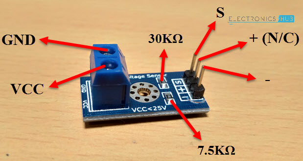
Voltage Sensor
The voltage sensor module extends the analog input range of the ADC to around 25V using a straightforward voltage divider network.
Code
| #include<reg51.h> |
| #define lcd P3 |
| #define dat P2 |
| sbit rs=P1^6; |
| sbit e=P1^7; |
| void delay (int); |
| void display (unsigned char); |
| void cmd (unsigned char); |
| void init (void); |
| void string (char *); |
| void intro (void); |
| char i=0; |
| void delay (int d) |
| { |
| unsigned char i=0; |
| for(;d>0;d–) |
| { |
| for(i=250;i>0;i–); |
| for(i=248;i>0;i–); |
| } |
| } |
| void cmd (unsigned char c) |
| { |
| lcd=c; |
| rs=0; |
| e=1; |
| delay(10); |
| e=0; |
| } |
| void display (unsigned char c) |
| { |
| lcd=c; |
| rs=1; |
| e=1; |
| delay(10); |
| e=0; |
| } |
| void string (char *c) |
| { |
| while(*c) |
| { |
| display(*c++); |
| } |
| } |
| void init (void) |
| { |
| cmd(0x38); |
| cmd(0x01); |
| cmd(0x0c); |
| cmd(0x80); |
| } |
| void intro (void) |
| { |
| string(” Electronics “); |
| cmd(0xc0); |
| string(” Hub “); |
| delay(2000); |
| cmd(0x01); |
| string(” Digital “); |
| cmd(0xc0); |
| string(” Voltmeter “); |
| delay(2000); |
| cmd(0x01); |
| cmd(0x80); |
| } |
| void main() |
| { |
| unsigned int temp=0; |
| unsigned int temp1=0; |
| float val=0.0; |
| init(); |
| intro(); |
| dat=0xff; |
| while(1) |
| { |
| if(i==0) |
| { |
| string(” Volts – “); |
| i++; |
| } |
| val=dat*0.02; // 0.02 is resolution of adc |
| val=val/0.2; // 0.2 is nothing but (R2/(R1+R2)) resistor values in the voltage sensor |
| cmd(0x89); |
| if((val>=1.0) && (val<10.0)) |
| { |
| display(‘ ‘); |
| temp=val*1000; |
| temp1=((temp/1000)+48); |
| display(temp1); |
| display(‘.’); |
| temp1=(((temp/100)%10)+48); |
| display(temp1); |
| } |
| else if((val>=10.0) && (val<100.0)) |
| { |
| temp=val*100; |
| temp1=((temp/1000)+48); |
| display(temp1); |
| temp1=(((temp/100)%10)+48); |
| display(temp1); |
| display(‘.’); |
| temp1=(((temp/10)%10)+48); |
| display(temp1); |
| } |
| else |
| { |
| display(‘ ‘); |
| string(“0.0”); |
| } |
| delay(1000); |
| } |
| while(1); |
| } |
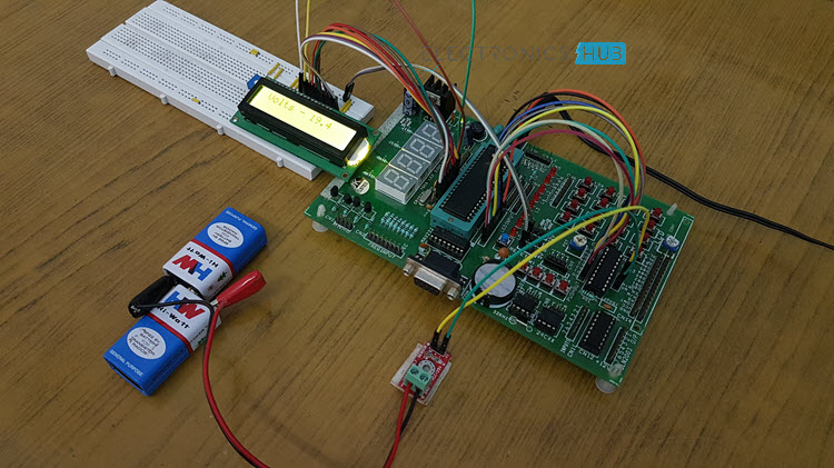
How does Digital Voltmeter Circuit work using an 8051 Microcontroller?
- Burn the software initially onto the at89c51 microcontroller.
- Give the connections now in accordance with the circuit diagram.
- Connect a battery or another source of voltage to the voltage sensor’s input.
- Verify that the maximum analog input voltage is no more than 25 V DC.
- Connect a digital multimeter to the voltage sensor’s input terminals.
- Turn on the board supply at this time.
- Now, notice that the same voltage is displayed by both the LCD and the digital multimeter (or very similar voltages).
- Try to gradually change the analog input voltage if at all possible. Now that both the multimeter and LCD are showing the same voltages, we can declare that the voltmeter is functioning properly.
- Deactivate the board supply.
Digital Voltmeter Circuit Applications
- Low voltage applications use this technique to measure voltage.
- used to measure the batteries in toys.
- With a small change, we may use this system to measure physical quantities such as temperature, humidity, gas, etc.
Digital Voltmeter Circuit Limitations
- The acceptable input analog voltage range is 0 to 5V.
- We can only measure one analog input value at a time with this system.
Digital Voltmeter Circuit using ICL7107
Without a microprocessor, a voltmeter can still be created. This is the voltmeter circuit utilizing the L7017 IC.
Here, we use a low-power three-and-a-half digit A/D converter (ICL7107) with inbuilt 7 segment decoders, display drivers, a reference, and a clock to create an analog-to-digital converter that doubles as a digital voltmeter.
The fact that this IC can directly drive a seven-segment display without needing separate decoding circuitry is a benefit. The circuit has a 200mV to 2V measurement range with a 0.001V resolution.
Principle Behind the Circuit
The idea behind this circuit is to use the ICL7107 as an analog to digital-converter. The entire process is split into two stages: decoding and analog to digital conversion.
The processes of integrating and reference integrating are used to convert analog to digital. In other words, the output of the integrator is first brought to a ramp signal by integrating the input signal, and then it is brought back to zero by integrating a reference voltage of the opposite polarity.
The resulting digital code is then decoded to power the display device utilising display decoders.
Digital Voltmeter Circuit Diagram using ICL7107

How Design Digital Voltmeter Circuit?
Designing the circuit requires an appropriate selection of the components as given below:
- Selection of Oscillation Circuit Components: The oscillating resistor and capacitor have been selected to have values of roughly 100K and 100pF, respectively, for a typical oscillating frequency of 48 KHz.
- Reference Capacitor: A reference capacitor with a value of between 0.1uF and 1uF is used. In this instance, we pick a 0.5uF electrolyte capacitor.
- A capacitor that automatically zeros out is chosen with a value between 0.01uF and 1uF. Here, a 0.1uF capacitor is chosen.
- Integrating Capacitor: An integral component of the integrating circuit is the integrating capacitor. The optimal integration current I, integrated voltage Vint, and integration period t all contribute to its value. The value of the capacitor is determined to be approximately 0.16uF for a time period of 83mSec, current of 4uA, and voltage of 2V. Pick a 0.22uF capacitor in this case.
- The full-scale analogue input voltage and the ideal integration current determine the value of the integrating resistor. For an input voltage of 2V at full scale, we choose a resistor of 500K.
How to Operate Digital Voltmeter Circuit?
The dual supply of +/- 5V is used to power the IC. The reference signal is established by changing the reference resistor once the circuit has been activated. About half of the input voltage must be the reference voltage. The resistor and capacitor that oscillate set the device’s oscillation or clock frequency.
A reference voltage has been applied to the reference capacitor. The auto zero capacitor is then charged in a feedback loop so that it can account for voltage variations. Later, the converter integrates the input differential voltage for a predetermined amount of time so that the integrator’s output is a ramp signal.
The integrator’s input is then supplied with a known reference voltage, which is allowed to ramp up until the output is zero. The digital reading is presented as: The time it takes for the output to return to zero is proportional to the input signal.
Display Count = 1000 * (Vin/Vref).
The digital count is then decoded to provide a seven segment compatible signal that can operate the displays. The multiplexed 7-segment display then shows the digital output.
Applications of Digital Voltmeter Circuit
- This circuit can offer a digital reading of the measured voltage in digital multimeters.
- Both AC and DC voltages are measurable with it.
- With the use of a transducer circuit and signal conditioning circuit, physical quantities such as pressure, temperature, and stress can be measured.
- Applications requiring high accuracy and high resolution can use it.
Limitations of Digital Voltmeter Circuit
- Only a small range of voltages can be measured by it.
- The IC in question is a highly static CMOS chip.
- A common mode error, or rollover error, can occur when the reference voltage for the negative and positive input voltages differ.
- In some cases, the output of the integrator can become saturated when using a full scale negative input voltage of 2V.
- The LED drivers’ internal heating can lead to performance degradation.
- The noise level is typically made louder by the reference temperature coefficient, internal chip dissipation, and package thermal resistance.