
I am text block. Click edit button to change this text. Lorem ipsum dolor sit amet, consectetur adipiscing elit. Ut elit tellus, luctus nec ullamcorper mattis, pulvinar dapibus leo.
-14%


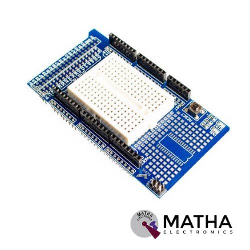
Prototype Shield V3.0 For Arduino Mega with breadboard
Original price was: ₹650.00.₹500.00Current price is: ₹500.00. inc. GST
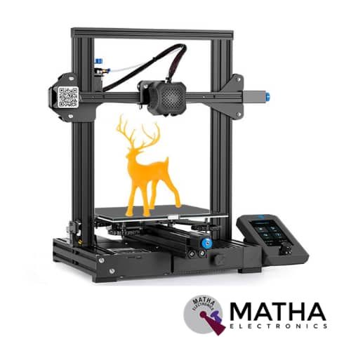
Creality Ender-3 V2 Upgraded 3D Printer with Silent Motherboard
Original price was: ₹27,000.00.₹25,000.00Current price is: ₹25,000.00. inc. GST
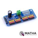
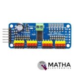
16-Channel 12-bit PWM/Servo Driver I2C interface PCA9685 for Arduino Raspberry Pi
Original price was: ₹700.00.₹600.00Current price is: ₹600.00. inc. GST
- Adjustable frequency PWM up to about 1.6 kHz
- 12-bit resolution for each output – for servos, that means about 4us resolution at a 60Hz update rate
- Configurable push-pull or an open-drain output
- The output enable pin to quickly disable all the outputs
- Terminal block for power input
- Reverse polarity protection on the terminal block input
- Green power-good LED
- 3 pin connectors in groups of 4 so you can plug in 16 servos at once
- Chainable design
- A spot to place a big capacitor on the V+ line
- 220-ohm series resistors on all the output lines to protect them, and to make driving LEDs trivial.
- This board/chip uses an I2C 7-bit address between 0x60-0x80, selectable with jumpers.
Description
PCA9685 is designed as a 16 channel 12-Bit PWM/Servo Controller, during which we are able to control 16 free-running PWM outputs with just two pins. Thereby greatly reducing the occupant I/Os. These drivers are widely utilized to make a robot that has several moving parts or if you would like to regulate too many LEDs with PWM outputs. During this case, the limited PWM outputs of your microcontroller cause an excellent big problem for you. Thus, this 16 channel PCA968512-Bit PWM/Servo Driver is the perfect solution for this problem. Moreover, it connects up to 62 driver boards in a cascade way. So it’ll be able to control 992 servos in total. This driver is an I2C-controlled PWM driver with an inbuilt clock. This indicates that there’s no ought to continuously send it to signal to hold up the microcontroller, it’s completely free running.
PCA9685 is designed as a 5v compliant device, that we will control it from a 3.3V microcontroller and still safely approach 6V outputs. This I2C-bus controlled LED controller is optimized for Red/Green/Blue/Amber (RGBA) colour backlighting applications. Each LED output provides an individual 12-bit resolution (4096 steps) PWM controller with a hard and fast frequency. The PCA9685 controller is designed to operate at a programmable frequency from a typical 24 Hz to 1526 Hz. It offers an adjustable duty cycle from 0% to 100%, in order that the LED set output a selected brightness. And also all the outputs are set to an equivalent PWM frequency. Additionally, PCA9685 allows staggered LED output on and off times to attenuate current surges. This on and off time delay are often programmed independently for every one of the 16 channels.
Reviews (0)
Shipping & Delivery

Related products
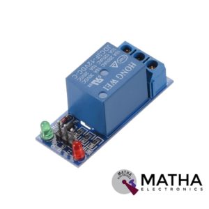
1 CHANNEL 12V RELAY
- 1-Channel relay interface board
- Operating voltage: 12V DC
- Provide high current relay of 15A
- For quick and easy connection high-quality screw terminals provided
- Can control both AC & DC appliances
- LED status indicates relay ON/OFF state.
- High current relay of 10A @250 V AC/10A@ 30V DC
- Standard interface that can be controlled by a microcontroller (Arduino, 8051, PIC, AVR, DSP, ARM)
- For easy accessibility input signal pin connected to burg sticks
- Dimension: 43*17*17mm
- Weight: 150gm

1 CHANNEL 5V RELAY
- 1 channel relay board
- Operating voltage: 5V
- Maximum current: 2 A
- Relay contact current capacity of 10A @250 V AC/10A@ 30V AC
- configured as SINGLE POLE DOUBLE THROW( SPDT)
- LED status indicates relay ON/OFF state.
- Standard TTL level logic controlled
- One normally closed and one normally opened contact
- Compatible with any 5V microcontroller
- Dimension: 43*17*17mm
- Weight: 150gm


DM556 Digital Stepper Motor Driver with Micro Stepping 20 to 50V 5.6A
- Good high-speed performance
- Supply voltage: +50VDC
- Output current from 0.5A to 5.6A
- Pulse input frequency up to 200 kHz
- Extremely cost-effective
- Automatic idle-current reduction
- Self-test and Auto-configuration technology TTL compatible and optically isolated input
- Micro step resolutions programmable, from full-step to 102,400 steps/rev
- Suitable for 2-phase and 4-phase motors
- Support PUL/DIR and CW/CCW modes
- Anti-Resonance provides optimum torque and nulls mid-range instability
- Extra-low motor noise offers excellent quietness
- Over-voltage, over-current protection and phase error protection
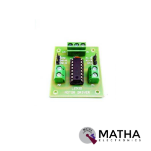
L293D MOTOR DRIVER
- Can be used to run two dc motors with the same IC
- Speed and direction control is possible
- Supply voltage: 4.5 V to 7V
- Motor voltage: 4.5 v to 36v
- Maximum peak motor current: 1.2 A
- Maximum continuous motor current: 600 milli ampere
- Screw terminal connectors for easy connection
- Transition time: 300 ns (at 5v and 24v)
- High noise immunity inputs
- Automatic thermal shutdown
- Available in 16 pin DIP, TSSOP, SOIC package
- Dimension: 48*34*14mm
- Weight: 15gm


L293D Motor Driver Shield
- L293D motor driver chip & 74HC595 shift register
- Four H-bridges
- Terminal blocks and jumper to connect external power, for separate logic/motor supplies
- Up to 4 bi-directional DC motors with individual 8-bit speed selection
- Up to 2 stepper motors (unipolar or bipolar) with single coil, double coil or interleaved stepping.
- 2 connections for 5V ‘hobby’ servos connected to the Arduino’s high-resolution dedicated timer
- 4 H-Bridges: L293D chipset provides 0.6A per bridge (1.2A peak) with thermal shutdown protection, internal kickback protection diodes. Can run motors on 4.5VDC to 25VDC.
- Pull-down resistors keep motors disabled during power-up
- Big terminal block connectors to easily hook up wires (18-26AWG) and power
- Arduino reset button brought up top
- Tested compatible with Arduino Mega 1280 & 2560, Diecimila, Duemilanove, and UNO
- PCB Size: 69 x 53 mm
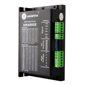
Leadshine DMA860E Stepper Motor Driver
- Model: DMA860E.
- Control Mode: Step & Direction.
- Max Input Frequency: 200 kHz.
- Input Voltage Range: 18 - 80 VAC / 24 - 110 VDC.
- Suggested Power Supply Voltage Range: 36-90 VDC /24-60 VAC.
- Number of DIP Switch Resolution Configurations: 16.
- 16 selectable micro-step resolutions of 400-51,200 via DIP switches.
- 8 selectable output current settings of 2.4 – 7.2A via DIP switches.
- Logic Current Range: 7-16mA (10mA typical).
- Logic Voltage Range: 4-5 VDC for pulse active high (default), or 0-0.5V for pulse active low.
- Pulse enabled at: Rising edge.
- Idle Current Percentage: 50 %.
- Number of Digital Inputs: 3.
- Step Width: 2,500 ns.
- Minimal Direction Setup Time: 5,000 ns.
- Isolation Resistance: 500M Ohm..
- Ambient Temperature: 0-50°C.
- Humidity: 40–95% RH.
- Operating Temperature: 0-70°C.
- Vibration: 5.9 m/s2 Max.
- Motor auto-identification and parameter auto-configuration for optimal torque from wide-range motors.
- Step & direction (PUL/DIR) and CW/CCW (via internal jumper set) control. Step & direction by default Multi-Stepping for smooth motor movement.
- Opto Isolation for input control signals.
- Soft-start with no “jump” when powered on.
- Protections for over-voltage and over-current.
- Dimension: 5.94 X 3.82 X 2.24 Inches.
- Weight: 1.13 lbs.
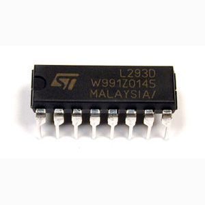
Motor Driver IC – L293D
- Can be used to run Two DC motors with the same IC.
- Speed and Direction control is possible
- Motor voltage Vcc2 (Vs): 4.5V to 36V
- Maximum Peak motor current: 1.2A
- Maximum Continuous Motor Current: 600mA
- Supply Voltage to Vcc1(vss): 4.5V to 7V
- Transition time: 300ns (at 5Vand 24V)
- Automatic Thermal shutdown is available
- Available in 16-pin DIP, TSSOP, SOIC packages
- Featuring Unit rode L293 and L293D
- Wide Supply-Voltage Range: 4.5 V to 36 V
- Separate Input-Logic Supply
- Internal ESD Protection
- Thermal Shutdown
- High-Noise-Immunity Inputs
- Output Current 1 A Per Channel (600 mA for L293D)
- Peak Output Current 2 A Per Channel (1.2 A for L293D)
- Output Clamp Diodes for Inductive Transient Suppression
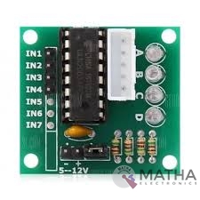
ULN2003 Driver
- Contains 7 high-voltage and high current Darlington pairs
- Each pair is rated for 50V and 500mA
- Input pins can be triggered by +5V
- All seven Output pins can be connected to gather to drive loads up to (7×500mA) ~3.5A.
- Can be directly controlled by logic devices like Digital Gates PIC etc
- Available in 16-pin DIP, TSSOP, SOIC packages
- Dimensions: 32 x 18 x 11mm (LxWxH)
- Weight: 3 gm
Reviews
There are no reviews yet.