
I am text block. Click edit button to change this text. Lorem ipsum dolor sit amet, consectetur adipiscing elit. Ut elit tellus, luctus nec ullamcorper mattis, pulvinar dapibus leo.
-12%

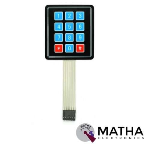
4*3 MATRIX KEYPAD
Original price was: ₹250.00.₹150.00Current price is: ₹150.00. inc. GST

5V USB OUTPUT CONVERTOR 7V-24V TO 5V/3A, DC-DC STEP DOWN BUCK KIS3R33S MODULE
Original price was: ₹600.00.₹400.00Current price is: ₹400.00. inc. GST
4*4 MATRIX KEYPAD
Original price was: ₹170.00.₹150.00Current price is: ₹150.00. inc. GST
The maximum voltage across each button: 24v
- The maximum current across each button: 3mA
- Easy communication with any microcontroller
- Ultra-thin design
- Adhesive backing provides easy integration
- High price-performance ratio
- Allows microcontroller to scan 8 output pins to check which 16 button
- Long life
- Maximum operating temperature: 0 degrees to 50 degrees Celsius
- Dimension: 70*77*1mm
- Weight: 7.5gm
Description
A Matrix keypad is a small compact input device that accepts user input and is processed by the microcontrollers. These keys are arranged as rows and columns. 4*4 matrix keypad is a non-encoded keypad consisting of 16keys in parallel with a built-in pushbutton that is connected to row and column. The keys of each row and column are connected through pins outside, pin Y1-Y4 to control rows, and pin X1-X4 to control columns. When the key has been pressed the row and column make contact with each other, otherwise, there is no communication between them. A microcontroller can scan these lines when a button is pressed. These are mainly used in controls systems, embedded systems, digital circuits, calculators, ATMs, etc.
When any key is pressed down, power is connected to rows, so they are High level. Then all the rows R1-R4 are set as Low and then detect the status of the columns. Any Low indication in the column means there is key pressing and that the key is among the 4 keys of the column. Whereas, If all columns are High, it means no key is pressed down. Afterwards in order to locate the key. As the pressed key column is identified, knowing the line would finalize the testing. Thus, set the rows as Low in turns until any is unveiled accordingly – other rows will still be High. Now the row can be identified. Detect the status of each column in turns. Thus column tested Low is the one intersecting with the line is just the key pressed.
Applications
- Security systems.
- Vending machines.
- Industrial machines.
- Engineering systems.
- Measuring instruments.
- Data entry for Embedded Systems
- Hobby projects.
- Basically any where INPUT device is needed
Additional information
| Color |
a ,b |
|---|
Reviews (0)
Shipping & Delivery

Related products

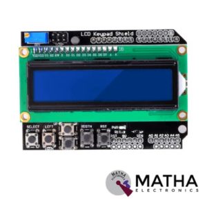
16×2 (1602) LCD Keypad Shield
- Operating Voltage:5V
- 5 Push buttons.
- RST button to reset Arduino program.
- Integrate a potentiometer for adjusting the backlight.
- Expanded available I/O pins.
- Blue light with white characters.
- Uses 4 Bit Arduino LCD Library
- Screen contrast adjustment
- Arduino Reset button
- The keypad consists of 6 keys select, up, right, down, left and reset.
- To save the digital IO pins, the keypad interface only uses one ADC channel.
- The key value is read out through a 5 stage voltage divider.
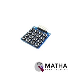

4×4 Keypad Board Matrix Keyboard 16 Key Buttons For Arduino
- 4×4 Matrix Keyboard Module with 16 buttons
- Small in size and hence Save space
- More convenient to use
- Expanded development application modules for single chip
- With 16 keys and an 8 pin
- The maximum voltage across each button: 24v
- The maximum current across each button: 3mA
- Easy communication with any microcontroller
- Ultra-thin design
- Adhesive backing provides easy integration
- High price-performance ratio
- Allows microcontroller to scan 8 output pins to check which 16 button
- Long life
- Maximum operating temperature: 0 degrees to 50 degrees Celsius
- Dimension: 70*77*1mm
- Weight: 7.5gm
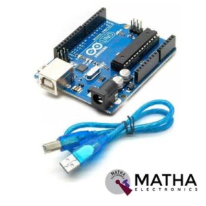

Arduino Duemilanove Development Board with USB Cable
- Microcontroller: ATmega168/ATmega 328
- Operating Voltage: 5V
- Input Voltage: 7-12V
- Input Voltage: 6-20V
- Digital I/O Pins: 14 (of which 6 provide PWM output)
- Analog Input Pins: 6
- DC Current per I/O Pin: 40 mA
- DC Current for 3.3V Pin: 50 mA
- Flash Memory: 16 KB (ATmega168) or 32 KB (ATmega328) of which 2 KB used by the bootloader
- SRAM: 1 KB (ATmega168) or 2 KB (ATmega328)
- EEPROM: 512 bytes (ATmega168) or 1 KB (ATmega328)
- Clock Speed: 16 MHz


CAN Bus Shield
- Implements CAN V2.0B at up to 1 Mb/s
- Industrial standard 9 pin sub-D connector
- OBD-II and CAN standard pinout selectable.
- Changeable chip select pin
- Changeable CS pin for TF card slot
- Changeable INT pin
- Screw terminal that easily to connect CAN_H and CAN_L
- Arduino Uno pin headers
- Grove connectors (I2C and UART)
- SPI Interface up to 10 MHz
- Standard (11 bit) and extended (29 bit) data and remote frames
- Two receive buffers with prioritized message storage


L293D Motor Driver Shield
- L293D motor driver chip & 74HC595 shift register
- Four H-bridges
- Terminal blocks and jumper to connect external power, for separate logic/motor supplies
- Up to 4 bi-directional DC motors with individual 8-bit speed selection
- Up to 2 stepper motors (unipolar or bipolar) with single coil, double coil or interleaved stepping.
- 2 connections for 5V ‘hobby’ servos connected to the Arduino’s high-resolution dedicated timer
- 4 H-Bridges: L293D chipset provides 0.6A per bridge (1.2A peak) with thermal shutdown protection, internal kickback protection diodes. Can run motors on 4.5VDC to 25VDC.
- Pull-down resistors keep motors disabled during power-up
- Big terminal block connectors to easily hook up wires (18-26AWG) and power
- Arduino reset button brought up top
- Tested compatible with Arduino Mega 1280 & 2560, Diecimila, Duemilanove, and UNO
- PCB Size: 69 x 53 mm
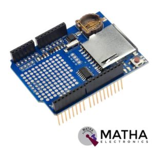

SD Card shield V4.0 for Arduino UNO
- Standard SD card, SDHC card and TF card compatible
- 3.3v and 5v logical voltage compatible
- 2.6-3.6v DC power supply
- UART Grove & I2C connection compatible
- Fully supported SD Library
- Minimal number of SPI port
- Jumpers provided for configuring Arduino SPI port pins
- Onboard toggle switch for SD card select type
- Truly stackable
- Prototype expand Library support
- Size: 53mm x 47mm
- Weight: 35g


Sensor Shield V5 Expansion Board For Arduino
- Retain the merits of the V4.0 version
- Laminated design
- PCB immersion gold processing technology
- IIC interface
- Bluetooth module communication interface
- SD card module communication interface
- APC220 Wireless RF modules communication interface
- RB URF v1.1 ultrasonic sensors interface
- 12864 LCD string of line and parallel interface
- 32 servo controller interface
Reviews
There are no reviews yet.