
I am text block. Click edit button to change this text. Lorem ipsum dolor sit amet, consectetur adipiscing elit. Ut elit tellus, luctus nec ullamcorper mattis, pulvinar dapibus leo.
-23%

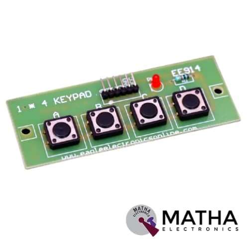
1x4 Key Matrix Switch Keypad
Original price was: ₹200.00.₹150.00Current price is: ₹150.00. inc. GST
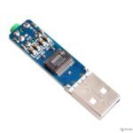
5V PCM2704 Sound Card Decoding Module DAC Decoder Board For PC Computer USB Powered
Original price was: ₹1,725.00.₹1,500.00Current price is: ₹1,500.00. inc. GST
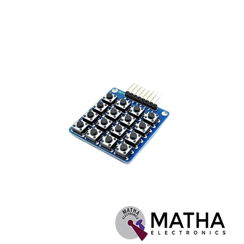
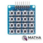
4×4 Keypad Board Matrix Keyboard 16 Key Buttons For Arduino
Original price was: ₹155.00.₹120.00Current price is: ₹120.00. inc. GST
- 4×4 Matrix Keyboard Module with 16 buttons
- Small in size and hence Save space
- More convenient to use
- Expanded development application modules for single chip
- With 16 keys and an 8 pin
- The maximum voltage across each button: 24v
- The maximum current across each button: 3mA
- Easy communication with any microcontroller
- Ultra-thin design
- Adhesive backing provides easy integration
- High price-performance ratio
- Allows microcontroller to scan 8 output pins to check which 16 button
- Long life
- Maximum operating temperature: 0 degrees to 50 degrees Celsius
- Dimension: 70*77*1mm
- Weight: 7.5gm
Description
A Matrix keypad is a small compact input device that accepts user input and is processed by the microcontrollers. These keys are arranged as rows and columns. 4*4 matrix keypad is a non-encoded keypad consisting of 16keys in parallel with a built-in pushbutton that is connected to row and column. . The keys of each row and column are connected through pins outside, pin Y1-Y4 to control rows, and pin X1-X4 to control columns. When the key has been pressed the row and column makes contact with each other, otherwise, there is no communication between them. A microcontroller can scan these lines when a button is pressed. These are mainly used in control systems, embedded systems, digital circuits, calculators, ATMs, etc. This 4×4 matrix keypad comes with microswitch buttons. Moreover, the module has four holes 3mm (M3) holes for mounting.
When any key is pressed down, power is connected to rows, so they are High level. Then all the rows R1-R4 are set as Low and then detect the status of the columns. Any Low indication in the column means there is key pressing and that the key is among the 4 keys of the column. Whereas, If all columns are High, it means no key is pressed down. Afterwards in order to locate the key. As the pressed key column is identified, knowing the line would finalize the testing. Thus, set the rows as Low in turns until any is unveiled accordingly – other rows will still be High. Now the row can be identified. Detect the status of each column in turns. Thus column tested Low is the one intersecting with the line is just the key pressed.
Reviews (0)
Shipping & Delivery

Related products

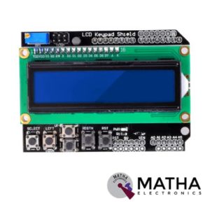
16×2 (1602) LCD Keypad Shield
- Operating Voltage:5V
- 5 Push buttons.
- RST button to reset Arduino program.
- Integrate a potentiometer for adjusting the backlight.
- Expanded available I/O pins.
- Blue light with white characters.
- Uses 4 Bit Arduino LCD Library
- Screen contrast adjustment
- Arduino Reset button
- The keypad consists of 6 keys select, up, right, down, left and reset.
- To save the digital IO pins, the keypad interface only uses one ADC channel.
- The key value is read out through a 5 stage voltage divider.

4*4 MATRIX KEYPAD
The maximum voltage across each button: 24v
- The maximum current across each button: 3mA
- Easy communication with any microcontroller
- Ultra-thin design
- Adhesive backing provides easy integration
- High price-performance ratio
- Allows microcontroller to scan 8 output pins to check which 16 button
- Long life
- Maximum operating temperature: 0 degrees to 50 degrees Celsius
- Dimension: 70*77*1mm
- Weight: 7.5gm
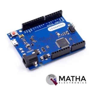

Arduino Leonardo R3
- Board Mode: LEONARDO R3
- Microcontroller: ATmega32u4
- Operating Voltage: 5V
- Input Voltage (Recommended): 7-12V
- Input Voltage (limits): 6-20V
- Digital I/O Pins: 20
- PWM Channels: 7
- Analog Input Channels: 12
- DC Current per I/O Pin: 40 mA
- DC Current for 3.3V Pin: 50 mA
- Flash Memory: 32 KB
- SRAM: 2.5 KB (ATmega32u4)
- EEPROM: 1 KB (ATmega32u4)
- Clock Speed: 16 MHz

NUCLEO-64 STM32G071RBT6 Development Board Arduino & ST Morpho Connectivity
- STM32 microcontroller in LQFP64 package
- 1 user LED shared with ARDUINO®
- 1 user and 1 reset push-buttons
- 768 kHz crystal oscillator
- Board connectors: ARDUINO Uno V3 expansion connectors morpho extension pin headers for full access to all STM32 I/Os
- Flexible power-supply options: ST-LINK, USB VBUS, or external sources
- On-board ST-LINK debugger/programmer with USB re-enumeration capability: mass storage, Virtual COM port and debug port
- Comprehensive free software libraries and examples available with the STM32Cube MCU Package
- Support of a wide choice of Integrated Development Environments (IDEs) including IAR Embedded Workbench®, MDK-ARM, and STM32CubeIDE
- Board-specific features
- External SMPS to generate Vcore logic supply
- 24 MHz HSE
- Board connectors: External SMPS experimentation dedicated connector Micro-AB or Mini-AB USB connector for the ST-LINKMIPI® debug connector
- Arm® Mbed Enabled™ compliant
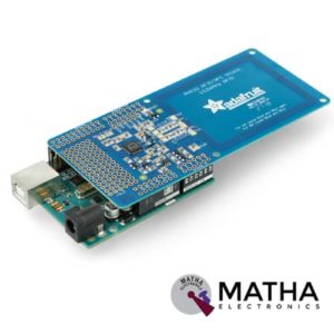

PN532 NFC/RFID Controller Shield for Arduino
- PN532 chip-set
- Operating Voltage : 3.3V ~ 5v
- Support I2C, SPI
- I2C: 3.3V ~ 24V TTL
- SPI: 3.3V TTL with 100-ohm resistors in series
- Plug and play, Arduino compatible
- Built-in PCB Antenna
- Communication distance:10cm
- Easy to change mode
- NFC/RFID PN532 shield including a tuned 13.56MHz stripline antenna
- 36-pin 0.1" header for attaching the shield to an Arduino.
- Compatible with Arduino Mega 1280 & 2560, Diecimila, Duemilanove, and UNO

STM32 Nucleo-64 development board with STM32F103RB MCU, supports Arduino and ST morpho connectivity
- STM32 microcontroller with LQFP64 package
- Two types of extension resources
- mbed-enabled (mbed.org)
- On-board ST-LINK/V2-1 debugger/programmer with SWD connector
- Flexible board power supply
- Three LEDs
- Two push buttons: USER and RESET
- USB re-enumeration capability: three different interfaces supported on USB
- Comprehensive free software HAL library including a variety of software examples
- Supported by wide choice of Integrated Development Environments (IDEs) including IAR, Keil, GCC-based IDEs
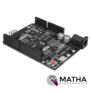

UNO R3 +WiFi ATmega328P+ESP8266 Module CH340G Compatible For Arduino Uno
- Microcontroller: ATmega328IC
- Wi-Fi: ESP8266
- USB-TTL converter: CH340G
- Power Output: 5V-800mA
- Power input USB: 5V (500mA max.)
- Power input VIN/DC Jack: 9-24V
- Power Consumption: 5V 800mA
- Logic Level: 5V
- WiFi: 802.11 b/g/n 2.4 GHz
- USB type: Micro USB
- USB Clock Frequency: 16MHz
- Operating Supply Voltage: 5V
- Digital I/O Pins: 14
- Analog I/O pins: 6
- Memory Size: 32Mb
- Interface Type: serial
- Operating temperature: −40С°/+125С°
- Dimensions (L×W)mm: 53.34×68.58


USB Host Shield
- Works with standard (dual 5/3.3V) and 3.3V-only (for example, Pro Arduino) boards.
- Operates over the extended -40°C to +85°C temperature range
- Complies with USB Specification Revision 2.0 (Full-Speed 12Mbps Peripheral, Full-/Low-Speed 12Mbps/1.5Mbps Host)
- Supports HID devices, such as keyboards, mice, joysticks, etc.
- Compatible with Mass storage devices, such as USB sticks, memory card readers, external hard drives (FAT32 Type File System – Mega Arduino only).
Reviews
There are no reviews yet.