
I am text block. Click edit button to change this text. Lorem ipsum dolor sit amet, consectetur adipiscing elit. Ut elit tellus, luctus nec ullamcorper mattis, pulvinar dapibus leo.
-9%
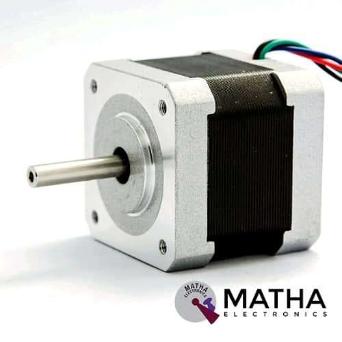
NEMA 17 1.6 kgcm
Original price was: ₹950.00.₹900.00Current price is: ₹900.00. inc. GST
DRV8825 Stepper Motor
Original price was: ₹300.00.₹275.00Current price is: ₹275.00. inc. GST
A4988 Stepper Motor
Original price was: ₹175.00.₹160.00Current price is: ₹160.00. inc. GST
- Operating voltage supply: 8 V to 35 V
- Continuous current per phase: 1 Amp
- Maximum current per phase: 2 Amp
- Minimum logic voltage: 3V
- Maximum logic voltage: 5.5V
- Microstep resolutions: Full, 1/2, 1/4, 1/8, and 1/16
- Logic Voltage supply: 3.3 V to 5 V
- Compatible with 3V3 and 5V microcontrollers
- Our Board comes with 0.1 Ohm Sensor resistors
- Five different step resolutions: full-step, half-step, quarter-step, eighth-step, and sixteenth-step
- The Correct current decay mode (fast decay or slow decay) is selected by chopping the control
- Over-temperature thermal shutdown, under-voltage lockout, and crossover-current protection
- Short-to-ground and shorted-load protection
- 4-layer, 2 oz copper PCB for improved heat dissipation
- Exposed solderable ground pad below the driver IC on the bottom of the PCB
Description
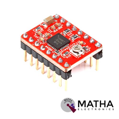
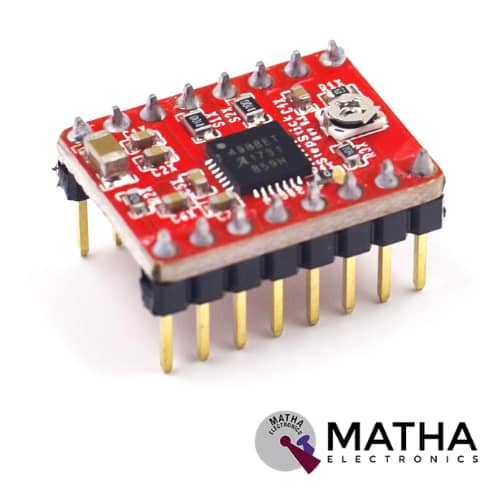
A4988 Module designed as a compact-sized, low-cost breakout board for Allegro’s A4988 Stepper Motor Driver. It offers numerous features such as adjustable current limiting, over-temperature, and over-current protection. It supports five different stepping resolutions and provides a wide operating voltage range from 8 volts to 35 volts. The A4988 is one of the prominent complete micro-stepping motor drivers with an inbuilt converter for ease of operation. These are designed specifically to operate bipolar stepper motors in full-, half-, quarter-, eighth-, and sixteenth-step modes, with an output drive capacity of up to 35 V and ±2 A. The A4988 Motor Driver has the ability to operate in Slow or Mixed decay modes by the presence of a fixed off-time current regulator
The inbuilt converter/translator performs the key to the easy implementation of the A4988. By simply inputting one pulse to the STEP input, drives the motor one micro-step. This motor driver does not consist of any phase sequence tables, high-frequency control lines, or complex interface to program. The A4988 motor driver is a perfect solution for applications where a complex microprocessor is unavailable or is overburdened. During stepping operation, the A4988 automatically selects the current decay mode, Slow or Mixed with the help of the chopping control.
Whereas in the Mixed decay mode, the initial device is set to a fast decay for a proportion of the fixed off-time, then shifts to a slow decay for the remainder of the off-time. As a result, the Mixed decay current control cause reduced audible motor noise, increased step accuracy, and reduced power dissipation. Moreover, it provides internal synchronous rectification control circuitry, thereby improving the pulse width modulation (PWM) power consumption during operation. Finally, the Internal circuit protection offers thermal shutdown with hysteresis, under-voltage lockout (UVLO), and crossover current protection. Don’t need special power-up sequencing.
Reviews (0)
Shipping & Delivery

Related products

5-36v Switch Drive High-power MOSFET Trigger Module
- Operating Voltage: DC 5V - 36V;
- The trigger source: digital high-low (DC3.3V - 20V), can be connected microcontroller IO port, PLC interfaces, DC power, you can access the PWM signal, the signal frequency 0--20KHZ perfect support.
- Output capacity: DC 5V - 36V, at room temperature, continuous current 15A, power 400W! Lower auxiliary cooling conditions, the maximum current up to 30A.
- Applications: You can control the output of power equipment, motors, light bulbs, LED lights, DC motors, micro-pumps, solenoid valves, etc.. You can enter
- PWM, motor speed control, lamp brightness.
- Availability: unlimited switch
- Operating temperature: -40-85
- Dimension: 34mm x 17mm x 12mm
- The use of imported dual-MOS parallel active output, lower resistance, more current, strong power at room temperature, 15A, 400W, to meet the most use of the equipment
- Wide voltage, the perfect support for PWM
- Easily control high power devices
- Input PWM to achieve motor speed control, lamp brightness control
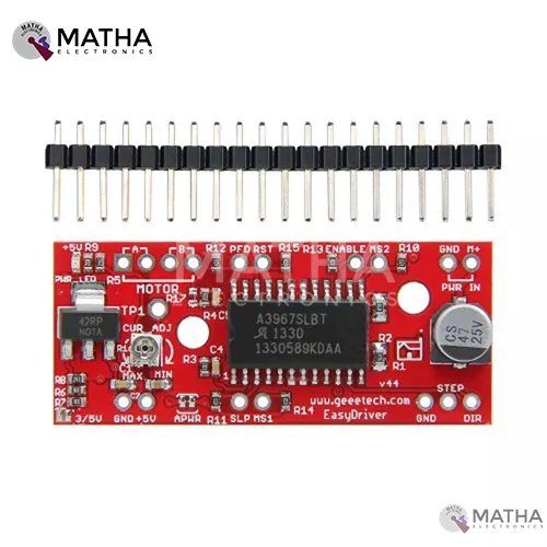
A3967 STEPPER MOTOR DRIVER
- A3967 precision micro-stepping driver
- Power supply: 7v to 30v
- Logic voltage: 5v to 3.3v
- Higher the voltage higher the torque at high speed
- Adjustable current control from 150Ma/ phase to 750ma phase
- Automatic current decay mode detection/selection
- Fast, slow, and mixed current decay modes
- Internal UVLO and thermal shutdown circuitry
- Crossover current protection
- Micro stepping resolution to full, half, quarter, and eighth steps by broken out MS1 and MS2 pins.
- Compatible with Arduino, GRBL G-Code interpreter for driving3-axis CNC machines
- Salington sink drivers used
- Compactible with 4, 6,8 wire stepper motor of any voltage

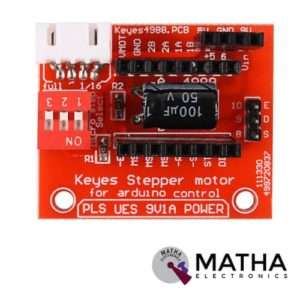
A4988 STEPPER MOTOR DRIVE CONTROLLER BOARD
- Operating voltage supply: 8 V to 35 V
- Continuous current per phase: 1 Amp
- Maximum current per phase: 2 Amp
- Minimum logic voltage: 3V
- Maximum logic voltage: 5.5V
- Microstep resolutions: Full, 1/2, 1/4, 1/8, and 1/16
- Compact size, easy to install and use.
- All jumpers hit the ON position to indicate 16 subdivisions (4988) or 32 subdivisions (8825).
- Jm connection motor; Jv Connects 5V and 12V-24V Power Supply.
- E /S /D /G of Jc corresponds to Enable /Step /Dir /Gnd driving signal output on the connection respectively.

Bullet Connector 3.5MM
- Diameter: 3.5mm
- Length:1.5CM & 1.5CM
- Amperage Rating: 60A -180Amps
- Hook up RC Battery to Electronic
- Hook up Brushless motor to electronic speed control
- These have low resistance and gives the best electric flow
- 5mm gold connectors Male
- 5mm gold connectors Female
- Dimension: 2.7*2.1*3inch
- Weight: 67gm

DRV8825 Stepper Motor
- Operating voltage: 8.2V to 45V
- Continuous current per phase: 1.5 Amp
- Maximum current per phase: 2.2 Amp
- Minimum logic voltage: 2.5V
- Maximum logic voltage: 5.25V
- Six different step resolutions: full-step, half-step, 1/4-step, 1/8-step, 1/16-step, and 1/32-step
- Compatible with 3V3 and 5V microcontrollers
- Our Board comes with 0.1 Ohm Sensor resistors
- The Correct current decay mode (fast decay or slow decay) selected by chopping control
- Over-temperature thermal shutdown, under-voltage lockout, and crossover-current protection
- Short-to-ground and shorted-load protection
- 4-layer, 2 oz copper PCB for improved heat dissipation
- Exposed solderable ground pad below the driver IC on the bottom of the PCB
- Dimensions : 15 x 20 mm.
- Weight: 4 gm.


IRF520 MOSFET DRIVER MODULE SENSOR
- Operating Voltage: 3.3v & 5v
- Digital level port
- Output load voltage: 0-24v
- Output load current: <5A
- The heat sink is added for currently more than 1A
- Compatible with Arduino, MCU, ARM, Raspberry pi
- PWM dimming LED used to step-less dimming, variable-speed motor
- Output PWM can be adjusted by the original IFR520 MOS
- Arduino can drive up to 24V, such as led lights, dc motors, miniature pumps, solenoid valves etc.
- Dimension:34*30*18mm
- Size: 10gm
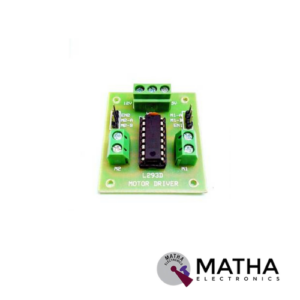
L293D MOTOR DRIVER
- Can be used to run two dc motors with the same IC
- Speed and direction control is possible
- Supply voltage: 4.5 V to 7V
- Motor voltage: 4.5 v to 36v
- Maximum peak motor current: 1.2 A
- Maximum continuous motor current: 600 milli ampere
- Screw terminal connectors for easy connection
- Transition time: 300 ns (at 5v and 24v)
- High noise immunity inputs
- Automatic thermal shutdown
- Available in 16 pin DIP, TSSOP, SOIC package
- Dimension: 48*34*14mm
- Weight: 15gm


MACH3 interface board
- Compatible Stepper Motor Driver - Max 5 2-phase Microstep controllers
- Driver type - Pulse and Direction signal control
- Wide input voltage range: 12-24V, and with anti-reverse function.
- Output 0-10V analogue voltage for the inverter to control the spindle speed.
- Compatible with MACH3, Linux CNC (EMC2) etc. parallel-control CNC software.
- USB power supply and peripherals power phase are separate to protect computer security.
- All the signals are to-isolate which can protect your computer security.
- 5-input interface to define the Limit, Emergence-Stop, Cutter alignment, etc.
- Wide input voltage range: 12-24V, and with anti-reverse function.
- One relay output control interface, accessed by the spindle motor or the air pump, water pump, etc.
- Maximum support 5-axis stepper motor driver controllers
- Output 0-10V analogue voltage for the inverter to control the spindle speed.
- All the way to the relay output port, control spindle switch. Output port P17 mouth.
- One relay output control interface, accessed by the spindle motor or the air pump, water pump, etc.
- Weight - Approx. 75g
- Dimensions - 90 * 70 * 20mm
Reviews
There are no reviews yet.