
I am text block. Click edit button to change this text. Lorem ipsum dolor sit amet, consectetur adipiscing elit. Ut elit tellus, luctus nec ullamcorper mattis, pulvinar dapibus leo.
-33%

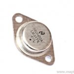
LM317K 1.2V to 37V Adjustable Voltage Regulator IC
Original price was: ₹120.00.₹80.00Current price is: ₹80.00. inc. GST
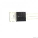
LM337 3-Terminal 1.5A Negative Adjustable Regulator IC
Original price was: ₹85.00.₹55.00Current price is: ₹55.00. inc. GST
CD4051 Single 8 Channel Analog Multiplexer or Demultiplexer IC
Original price was: ₹30.00.₹20.00Current price is: ₹20.00. inc. GST
- Single 8 Channel Analog Multiplexer or Demultiplexer
- Supply Voltage Range: 3 to 20V
- Input Current: ±10mA
- Power Dissipation: 500mW
- On State Resistance Max.: 1050Ω
- Low level Input Voltage Max.: 1.5V
- High level Input Voltage Min.: 3.5V
- Propagation Delay Time Max.: 60ns
- Package: DIP-16
Description
The CD4051 analog multiplexers/demultiplexers come as digitally controlled analog switches. They feature a low “ON” impedance and very low “OFF” leakage currents. Moreover, the Control of analog signals up to 15Vp-p achieved via digital signal amplitudes of 3−15V. For example, if VDD = 5V, VSS = 0V and VEE = −5V, analog signals from −5V to +5V can be controlled via digital inputs of 0−5V.
Over the entire VDDVSS and VDDVEE supply voltage ranges, the MUX/DEMUX circuits dissipate very little quiescent power. Which is independent of the control signals’ logic state. All channels are “OFF” when a logical “1” is present at the inhibit input terminal. With three binary control inputs, the CD4051BC is a single 8-channel multiplexer. A, B, and C, as well as a disable input. The three binary signals select 1 of 8 channels to be turned “ON” and connect the input to the output. Meanwhile, the IC’s output is always TTL, making it simple to interface with other TTL devices and microcontrollers. Thermal overload protection and ESD protection are among the many features included in the IC.
A multiplexer is a logic circuit that connects one or more input lines to a single common output line. The select lines decide which inputs are connected to which outputs, as well as how much data may be transferred over a network in a given amount of time. A combinational logic device that switches one common input line to one of several independent output lines is known as a decoder/demultiplexer. So, A demultiplexer is a device that converts a serial data signal to parallel data on its output lines.
Application
- Multiplexer and Demultiplxer circuit
- A/D and D/A converter circuits
- Network switching
- Programmable Logic circuits.
Reviews (0)
Shipping & Delivery

Related products

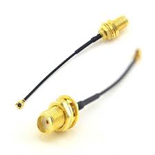
650NM Laser Diode
- Wavelength: 650nm
- Output optical power: 5mW
- Operating voltage: 5V
- Operating current: ~30mA
- Input current: 30mA
- Housing material: Copper
- Power lead length: 120mm.
- Transmit power: 58mW
- Spot: size 10mm to 15mm at 15meters
- Life span more than 2000 hours
- Driver circuit: APC circuit
- Small size
- Cost-effective
- Breadboard friendly
- Operating temperature -10°C to 40°C
- Dimension: :15mm x 6mm
- Weight: 10 grams
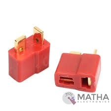
Dean Connector
- Male plug size: About 13* 7* 19mm
- Female plug size: About 13* 7* 15mm
- Current Rating: 30Amps
- Colour: Red and golden
- Material: Plastic and metal
- Provides a secure connection for battery and motor connections
- Eliminates the possibility of wrong polarity connections
- Used in RC hobby, car, boat, plane, helicopter, LIPO battery, etc.
- Dimension: 9x0.7x2cm
- Weight:20gm


Dual Micro USB 3.7v to 5V 2A Power Bank DIY 18650 LiPo Charger
- 4-level LED lamp display power, not working state intelligent automatic shutdown;
- The built-in lithium battery protection IC, over-current, under-voltage protection;
- Dual USB output ports.
- Dimensions: 68 x 34 x 9 mm (LxWxH)
- Weight: 10 gm
- Input port: MicroUSB (Andro)
- Input requirements: 5V constant voltage power supply can do charge input power, the most matching charger for 5v1a above
- Output port: USB
- Output parameters: 5V1A/5V2A
- Requirements for rechargeable batteries:
- Compatible Batteries: 18650 batteries, cell phone batteries, flat-panel batteries, MP3 batteries, etc. 3.7v-4.2V polymer Lithium battery,

HX711–24 Bit Analog to Digital Converter (ADC)
- It is an ADC converter with two differential input channels
- An active-low noise PGA is integrated inside the chip which provides the gain of 32, 64 and 128
- It has a power-on-reset capability which simplifies digital interface initialization.
- All controls to the IC are made through the pins. Programming is not needed.
- You can select a data rate of 10SPS or 80SPS at the output.
- Provides simultaneous supply rejection of 50Hz and 60Hz supply.
- Built-in analog power supply regulator
- The voltage supply range is from 2.6V to 5.5V
- The temperature range is from -40 °C to +85℃

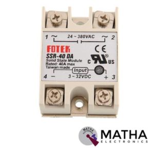
Solid State Relay Module DC To AC SSR-40DA 3-32VDC/24-380VAC 40A
- Control mode: DC-AC
- Input voltage: 3-32V DC.
- Output voltage: 24-380V AC.
- Output current: 40A.
- Working voltage: 250V.
- Material: plastic + metal.
- Loading current: 40A
- Control current: 3-25mA DC
- On voltage: ≤1.5V AC
- One-off Time: ≤10ms
- Off Leakage Current: ≤2mA
- Dielectrics voltage-resistance: 2500VAC
- Environment temperature: -30 to +75
- Long service life and high reliability.
- Reduced electromagnetic interference.
- Highly reliable, compact size designed to offer users maximum simplicity.
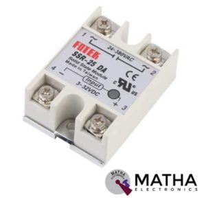
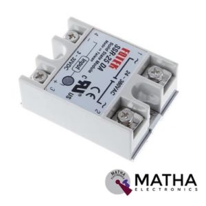
Solid State Relay Module SSR-25DA 25A /250V 3-32V DC Input 24-380VAC Output
- Control mode: DC-AC
- Input voltage: 3-32V DC.
- Output voltage: 24-380V AC.
- Output current: 25A.
- Working voltage: 250V.
- Material: plastic + metal.
- Environment temperature: -30 to +75
- Long service life and high reliability.
- Reduced electromagnetic interference.
- Highly reliable, compact size designed to offer users maximum simplicity.
- Dimension: 6. 5Cm x 4. 5Cm x 2. 2Cm


TP5100 4.2v 8.4v Single Double Lithium Battery Charge Management Li-ion Battery Compatible 2A Charging Board
- Input voltage: 5-15V DC power supply.
- Charge status: full and unloaded blue lights, charging red.
- Double 8.4v / 4.2v lithium rechargeable single .
- Programmable charge current. 0. 1A-2A .
- Programmable steady precharge current 10% -100%.
- Wide operating voltage, maximum reach I8V.
- Red and green LED charge status indicator.
- Chip temperature protection, overcurrent protection, under voltage protection.
- Battery temperature protection, reverse battery shutdown, short circuit protection.
- Switching frequency 400Khz, usable inductance 20uH and more.
- PWR_ON Power battery for switching control.
Reviews
There are no reviews yet.