
I am text block. Click edit button to change this text. Lorem ipsum dolor sit amet, consectetur adipiscing elit. Ut elit tellus, luctus nec ullamcorper mattis, pulvinar dapibus leo.
-18%
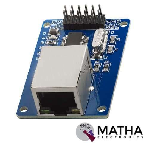
ENC28J60 ETHERNET MODULE
Original price was: ₹900.00.₹699.00Current price is: ₹699.00. inc. GST

ESP8266-12E 10A 220V NETWORK RELAY WIFI MODULE INPUT DC 7V-30V
Original price was: ₹2,000.00.₹1,500.00Current price is: ₹1,500.00. inc. GST
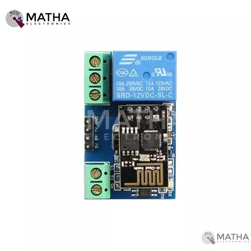
ESP8266- 01 5V WIFI RELAY MODULE TOI APP CONTROLLED FOR SMART HOME AUTOMATION
Original price was: ₹850.00.₹699.00Current price is: ₹699.00. inc. GST
- Onboad module: ESP2866 WIFI module
- Onboard relay: 5v.10a/250v ac, 10a/30v dc
- Can connect 5 clients at the same time on AP mode
- The module has two work modes: Cell phone, carry on Wi-Fi module and Cell phone and Wi-Fi module carry on the same router
- Used in mobile phone, Wi-Fi module equipped with one router and control relay by APP
- Maximum transmission distance of 400 m when cell phone carry on wifi module directly, in the open environment
- Transmission distance depends on routers signal intensity when wifi and cell phone is carrying on the same router
- IN+, IN_: 5V power input
- TX, RX, and GND: serial port debug pins
- Baud rate: 115200
- Provide diode effusion protection
- Short response time
- Dimension: 45*28mm
Description
ESP8266 Wi-Fi module is a single-channel relay module used to activate up to 250 V AC & 30VDC, which allows building in device control, lights, or triggering system when the module is supplied with the signal of ESP8266. It consists of an ESP8266 Wi-Fi module and microcontroller. The serial port instruction sent to the cell phone APP and for wireless control relay, a local area network implemented (LAN). This onboard module can connect up to 5 clients at the same time in the APP mode.
This module used to control larger voltage in the projects through Wi-Fi. The module comes with an onboard LED that indicates the state of the module. A red power LED activates when a signal received on the IN pin. When a signal received an audible click heard as the relay triggers, connecting the output pins. The relay controlled via the included ESP8266 that require configuration via UART to prior to full operation. Once programmed and powered it looks after itself, making it perfect for use in internet of things “IOT” based projects. This Wi-Fi module operates in 3 modes: STA (client), APP (hot), STA+APP (client +hot). Based on the work of the module to select correspond Wi-Fi module mode of operation. This module uses serial debugging software on a computer and USB to TTL module to transmit AT commands to configure the Wi-Fi module.
ESP8266 ESP-01 is a compact-sized, ultra-low power,32-bit MCU micro. This module supports standard IEEE802.11 b/g/n agreement, complete TCP/IP protocol stack. Users can use the add modules function to an existing device networking or building a separate network controller. Moreover, the ESP8266 is an extremely cost-effective board with a huge, and ever-growing, community with a full TCP/IP stack and MCU capability.
Reviews (0)
Shipping & Delivery

Related products

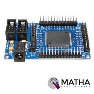
EP2C5T144 Altera Cyclone II FPGA Mini Development Board
- Onboard the EP2C5T144 chip.
- EPROM chip configuration using EPCS4, the size of 4Mbit.
- Onboard 50M active patch crystal (Crystal Slaughter halfback).
- Power supply with a largemouth outlet, single 5V power supply.
- Board has a power indicator and resets the switch.
- Onboard 3 SMD LED, the LED test can be done an experiment, more experiments using lead to complete.
- More IO ports and clock pins through the pin leads through these interfaces can be extended to any memory and peripherals.
- Board using a high-quality tantalum capacitor power filter.
- Support NiosII embedded CPU development.
- Board Dimension (LxWxH) mm: 72 x 52 x 13mm.
- Weight: 26gm.

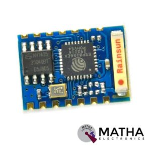
ESP8266 ESP – 03 WIFI Transreceiver Wireless Module
- Communication interface voltage: 3.3V
- Working current: 240mA(MAX)
- 802.11 b/g/n
- Wi-Fi Direct (P2P), soft-AP
- Integrated TCP/IP protocol stack
- Integrated TR switch, balun, LNA, power amplifier and matching network
- Integrated PLLs, regulators, DCXO and power management units
- +19.5dBm output power in 802.11b mode
- Power down leakage current of <10uA
- Integrated low power 32-bit CPU could be used as application processor
- SDIO 1.1/2.0, SPI, UART
- STBC, 1×1 MIMO, 2×1 MIMO
- A-MPDU & A-MSDU aggregation & 0.4ms guard interval
- Wake up and transmit packets in < 2ms
- Standby power consumption of < 1.0mW (DTIM3)
- SDIO 2.0, SPI, UART
- 32-pin QFN package
- Integrated RF switch, balun, 24dBm PA, DCXO, and PMU
- Integrated RISC processor, on-chip memory and external memory interfaces
- Integrated MAC/baseband processors
- Quality of Service management
- I2S interface for high fidelity audio applications
- On-chip low-dropout linear regulators for all internal supplies
- Proprietary spurious-free clock generation architecture
- Integrated WEP, TKIP, AES, and WAPI engines
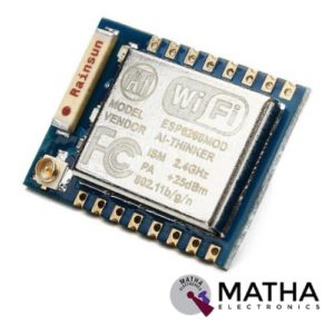
ESP8266 ESP – 07
- Smallest 802.11b/g/n Wi-Fi SOC module
- Low power 32-bit CPU, can also serve as the application processor
- Up to 160MHz clock speed
- Built-in 10 bit high precision ADC
- Supports UART/GPIO/IIC/PWM/ADC
- SMD-16 package for easy welding
- Integrated Wi-Fi MAC/BB/RF/PA/LNA
- Deep sleep current as low as 20uA
- Embedded LWIP protocol stack
- Supports STA/AP/STA + AP operation mode
- Support Smart Config/AirKiss technology
- UART baudrate up to 4Mbps
- General AT commands can be used quickly
- Supports remote firmware upgrade (FOTA)
- WIFI Direct (P2P),SOFT-AP
- Built-in TCP/IP
- The AT command is perfect, efficient, concise
- Support three modes: AP, STA and AP+STA coexistence mode
- Onboard Chip Antenna
- +19.5dBm output power in 802.11b mode
- Power down leakage current of <10uA
- SDIO 1.1/2.0, SPI, UART
- STBC, 1×1 MIMO, 2×1 MIMO
- A-MPDU & A-MSDU aggregation & 0.4ms guard interval
- Wake up and transmit packets in < 2ms
- Standby power consumption of < 1.0mW (DTIM3)

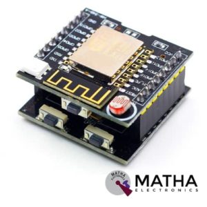
ESP8266 Serial WIFI Witty Cloud Development Board ESP-12F Module MINI Nodemcu
- LDR Light Sensor on board
- WS2812 Led on board
- 3x tactile buttons (1x in the Witty board and 2x in theCH340 board)
- Micro USB connection for power and/or programming
- Uses latest ESP-12F module with 4M flash and integrated antenna
- Includes CH340G USB-to-UART programmer
- Includes LDR (light dependent resistor a.k.a photoresistor) connected to ESP’s ADC pin
- RGB LED connected to GPIO 12,13 and 15
- It supports 3 modes AP, STA, AP+STA


NODMCU Esp8266-12 USB CP2102
- 11 b/g/n Wi-Fi Direct (P2P), soft-AP
- Integrated TCP/IP protocol stack
- CP2102 Serial / USB Chip
- +19.5dBm output power in 802.11b mode
- 4MB Flash Memory
- Integrated low power 32-bit CPU
- SDIO 1.1 / 2.0, SPI, UART
- Dimensions – 49 x 24.5 x 13mm
- Integrated TR switch, balun, LNA, power amplifier and matching network
- Integrated PLLs, regulators, DCXO and power management units
- On board USB to serial chip to easily program and upload codes from the Arduino IDE
- Embeds logic level converter circuits
- Has on board 3.3V regulator to ensure enough power to function as your go-to WiFi chip!
- Easy access to the GPIO pins for easy prototyping
- ESP-12E Processor
- Easy to use breadboard friendly form factor
- Voltage Regulator / Converter, excellent DC to DC conversion, super efficientESP-12E Processor
- Easy to use breadboard friendly form factor
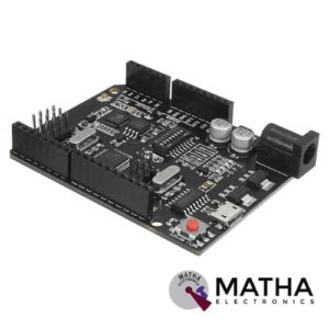

UNO R3 +WiFi ATmega328P+ESP8266 Module CH340G Compatible For Arduino Uno
- Microcontroller: ATmega328IC
- Wi-Fi: ESP8266
- USB-TTL converter: CH340G
- Power Output: 5V-800mA
- Power input USB: 5V (500mA max.)
- Power input VIN/DC Jack: 9-24V
- Power Consumption: 5V 800mA
- Logic Level: 5V
- WiFi: 802.11 b/g/n 2.4 GHz
- USB type: Micro USB
- USB Clock Frequency: 16MHz
- Operating Supply Voltage: 5V
- Digital I/O Pins: 14
- Analog I/O pins: 6
- Memory Size: 32Mb
- Interface Type: serial
- Operating temperature: −40С°/+125С°
- Dimensions (L×W)mm: 53.34×68.58
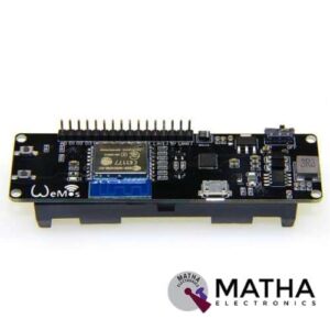
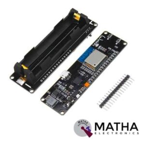
WeMos D1 ESP Wroom 02 Board ESP8266 Mini WiFi Nodemcu Module 18650 Battery
- One AD inputs.
- Micro USB inputs.
- One programmable LED (D0).
- AUTO PROGRAM circuit.
- ESP8266 (ESP-WROOM-02 With TELEC) is equivalent to the NodeMCU.
- Analog Input (AD): Built-in dividing resistor (AD = 220K ADC 100K = GND).
- There is a SOLDER terminal for SLEEP MODE.
- Compatible With Arduino andNodeMCU.
- Operation and charging are possible at the same time.
- 18650 charging circuit including the 5V boosting circuit with TP5410.
- Overcharge protection, over-discharge protection built-in.
- LED: Red = Charging, Green = Full charging.
- 3000 mA 18650 It is possible to operate for more than 17 hours on a battery.
- Integrated 18650 battery charging and discharging system.
- One switch controls whether the 18650 battery is on power or not.
- OLEDs SDA and SCL can connect to the D1 pin and the D2 pin respectively.
- The five buttons can be controlled by FLATH, RSET, D5, D6, and D7 respectively.
- The 5 Digital pins can configure the write/read/interrupt/PWM/I2C/one-wire supported separately.
- Operation and NodeMCU consistent, adding a programmable LED, you can use GPIO16 to control; display 8266 running status and other functions. Integrated OLED and five buttons, more convenient for development.
- The design concept originates from the open-source project NodeMCU; the development board integrates 18650 charging and discharging systems with charging and discharging protection. At the same time, an OLED and five directional buttons are integrated to facilitate the development.
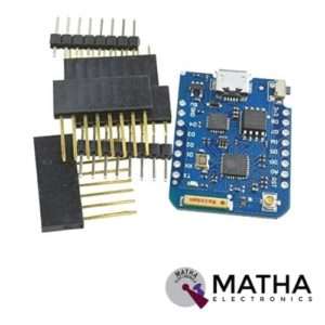
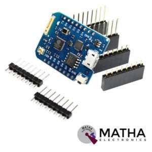
Reviews
There are no reviews yet.