
I am text block. Click edit button to change this text. Lorem ipsum dolor sit amet, consectetur adipiscing elit. Ut elit tellus, luctus nec ullamcorper mattis, pulvinar dapibus leo.
-13%

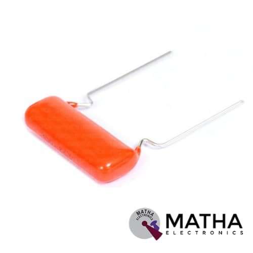
0.1uf 630V PPC Polyester Capacitor
Original price was: ₹17.00.₹12.00Current price is: ₹12.00. inc. GST
4A DPDT ON ON Rocker Switch Screw Type
Original price was: ₹20.00.₹15.00Current price is: ₹15.00. inc. GST
HT12D Decoder IC
Original price was: ₹75.00.₹65.00Current price is: ₹65.00. inc. GST
- 212 Series of Decoder
- Standby Current Max.: 4µA
- Operating Voltage Max.: 12V
- Operating Current Max.: 400µA
- Output Drive Current: 1.6mA
- Oscillator Frequency: 150kHz
- Supply Voltage Range: 2.4V to 12V
- Pins: 8 Address Pin, 4 Data Pin
- Package: DIP-18
Description
The HT12D Decoder IC designed to used only with its pair HT12E. These two ICs together form an Encoder and Decoder pair. These are 12-bit Encoders/Decoders, which means they can send and receive 12-bit data. However, the decoder IC should not connect with another decoder IC, therefore an Encoder and Decoder IC pair will share an 8-bit data address. So, out of these 12-bits, 8 are utilised to set address and 4 are used to send data.
Using these 4-bit data, we can create 16 types (2^4 =16) of combinations. These IC’s widely used with RF pairs or IR pairs. This IC pair will be ideal for applications that need the transmission of 4-bit data from one end to the other by wire or wireless. RF and IR modules communicate directly with microcontrollers, necessitating some advanced programming. It comes in two sizes: 18 and 20 pins, with just 18 working pins in each.
The HT12D’s main aim is to decode a 12-bit signal and send it out through the output pin. It is quite simple to make this IC operate because it has an in-built oscillator. The earth pin (pin 9) is grounded, and the IC is powered by +5V. To enable transmission, pull the Transmission Enable pin (pin 14) to the ground. The IC will need an oscillator to decode data; fortunately, this IC already has one. To activate it, just connect the OSC1 and OSC2 (pins 15 and 16) with a 470k resistor. Pins AD0 to AD1 can be used to acquire 4-bit data, while pins A0 to A7 must be used to create an 8-bit address. It’s a fantastic idea.
Applications
- Remote control systems
- IOT
- Smoke and builder alarm system
Reviews (0)
Shipping & Delivery

Related products


1/4W 5% Assorted Value Carbon Film Resistor Assortment Kit Set pack electronic diy kit
- 100% brand new and high quality.
- Fine workmanship and long service life.
- 1/4W carbon film resistor package.
- High precision and stability.
- Easy to use.
- Precision: 5%
- Error: 5%
- Values
- 10Ω, 15Ω, 22Ω, 33Ω, 47Ω, 68Ω, 100Ω, 220Ω, 330Ω, 470Ω, 1k, 1k5, 2k2, 3k3, 4k7, 5k6, 6K8, 8K2, 10K, 15K, 22K, 33K, 47K, 56K, 68K, 100K, 150K, 220K, 330K, 470K
- Package included: 150pcs

5-36v Switch Drive High-power MOSFET Trigger Module
- Operating Voltage: DC 5V - 36V;
- The trigger source: digital high-low (DC3.3V - 20V), can be connected microcontroller IO port, PLC interfaces, DC power, you can access the PWM signal, the signal frequency 0--20KHZ perfect support.
- Output capacity: DC 5V - 36V, at room temperature, continuous current 15A, power 400W! Lower auxiliary cooling conditions, the maximum current up to 30A.
- Applications: You can control the output of power equipment, motors, light bulbs, LED lights, DC motors, micro-pumps, solenoid valves, etc.. You can enter
- PWM, motor speed control, lamp brightness.
- Availability: unlimited switch
- Operating temperature: -40-85
- Dimension: 34mm x 17mm x 12mm
- The use of imported dual-MOS parallel active output, lower resistance, more current, strong power at room temperature, 15A, 400W, to meet the most use of the equipment
- Wide voltage, the perfect support for PWM
- Easily control high power devices
- Input PWM to achieve motor speed control, lamp brightness control


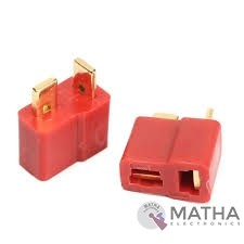
Dean Connector
- Male plug size: About 13* 7* 19mm
- Female plug size: About 13* 7* 15mm
- Current Rating: 30Amps
- Colour: Red and golden
- Material: Plastic and metal
- Provides a secure connection for battery and motor connections
- Eliminates the possibility of wrong polarity connections
- Used in RC hobby, car, boat, plane, helicopter, LIPO battery, etc.
- Dimension: 9x0.7x2cm
- Weight:20gm
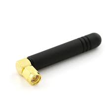
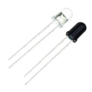
IR LED Sensor
- Size: 5mm LED
- Wavelength: 940nm wavelength (most commonly used)
- Forward current (IF) is 100mA (normal condition) and 300mA (max.)
- 5A of surge forward current
- 24v to 1.4v of forward voltage
- Temperature : -40 to 100 ℃
- Soldering Temperature should not exceed 260 ℃
- Power Dissipation of 150mW at 25℃ (free-air temperature) or below
- Spectral bandwidth of 45nm
- Viewing angle: 30 to 40 degree
- High Reliability
- Excessive radiant intensity
- Having lead spacing of 2.54mm
- Easy to use with breadboard or perf board
Reviews
There are no reviews yet.