
I am text block. Click edit button to change this text. Lorem ipsum dolor sit amet, consectetur adipiscing elit. Ut elit tellus, luctus nec ullamcorper mattis, pulvinar dapibus leo.
-25%


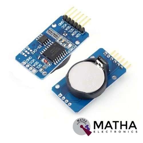
DS3231 RTC MODULE
Original price was: ₹500.00.₹375.00Current price is: ₹375.00. inc. GST
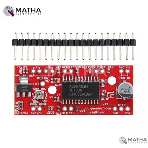
A3967 STEPPER MOTOR DRIVER
Original price was: ₹350.00.₹300.00Current price is: ₹300.00. inc. GST
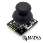
JOYSTICK MODULE
Original price was: ₹200.00.₹150.00Current price is: ₹150.00. inc. GST
- Operating voltage: 5V
- 5 pin module
- Long life
- High stable performance
- Directional movements controlled by a potentiometer
- Internal potentiometer value: 10k
- Compatible with Arduino interface
- Operating temperatures: 0 to 70 degrees
- Widely used in Arduino DIY projects
- Dimension: 1.57*1.02*1.26 inch
Description
The joystick module in an electronic system is the same as the analogue joystick found in the gamepad. It is an affordable solution for Arduino-based DIY projects and robot control etc. The joystick module is constructed by mounting two potentiometers at a 90-degree angle and hence can be used to sense movements in X & Y direction. These potentiometers are connected to short sticks centred by springs, and thus generating an output of around 2.5v from x and y when in a resting position. The output varies from 0V to 5 v when the joystick moves. When the joystick is connected to a microcontroller a value of 512 is expected in the resting position and when the joystick moves value varies from 0 to 1023. The joystick offers a wide range of applications such as for controlling outputs such as a melody or pixels on a screen. And also used for navigation or game control.
In this Joystick Module, the position coordinates measurement on the X and Y axis is performed by moving the “hat”. The hat is the inbuilt switch activated by pressing the stick. The X and Y axes were designed with two 10k potentiometers to control 2D movement by generating analogue signals. The two potentiometers on the joystick connect to analogue pins A0 and A1 on your microcontroller. When the module is in working mode, it will output two analogue values, Y-axis movement of the joystick produces a proportional analogue voltage on analogue pin 0. Similarly, the horizontal movement of the joystick can be tracked on analogue pin 1.
Pin Configuration:
- And: Ground terminal of Module
- +5v: Positive supply terminal of Module
- VRx: Voltage Proportional to X-axis
- VRy: Voltage Proportional to Y-axis
- SW: Switch
Reviews (0)
Shipping & Delivery

Related products

1 CHANNEL 5V RELAY
- 1 channel relay board
- Operating voltage: 5V
- Maximum current: 2 A
- Relay contact current capacity of 10A @250 V AC/10A@ 30V AC
- configured as SINGLE POLE DOUBLE THROW( SPDT)
- LED status indicates relay ON/OFF state.
- Standard TTL level logic controlled
- One normally closed and one normally opened contact
- Compatible with any 5V microcontroller
- Dimension: 43*17*17mm
- Weight: 150gm


2 CHANNEL 5V RELAY
- High current relay
- Two LED S to indicate relays ON/OFF status
- Low-level trigger expansion board
- Opto isolation circuitry
- Works with logic level signal 3.3V or 5V devices
- Can be used as normally open (NO) or normally closed (NC)
- Back EMF protection
- Ensures diode current protection
- AC control voltage: 250v @mx10A
- DC control voltage: 30V @max 10A
- Easy installation and fixing


4*3 MATRIX KEYPAD
- Operating voltage: 12V DC
- The maximum voltage across each button: 24v
- The maximum current across each button: 3mA
- Ultra-thin design
- Adhesive backing provides easy integration
- Easy communication with any microcontroller
- Flexible
- Only 7 microcontroller pins required to access 12 keys
- High price-performance ratio
- Allows microcontroller to scan 8 output pins to check which 16 button
- Long life
- Maximum operating temperature: 0 degrees to 50 degrees Celsius
- Dimension: 70*77*1mm
- Weight: 7.5gm
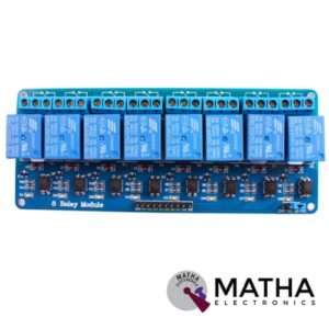
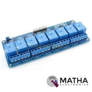
8 CHANNEL 5V RELAY
- Relay operating voltage: 5V
- 8 channel
- High impedance controller pin
- One normally closed contact and one normally opened
- Useful for appliances control
- Power supply indicator and control indicator lamp
- Pull-down circuit to avoid malfunction
- Can control both DC and AC to 220v AC load
- Works with both 3.3 V and 5 V logic with the less current drive
- 3 terminals per SPDT relay
- Standard interface can be directly controlled by a microcontroller like Arduino, 8051, AVR, PIC, DSP, ARM, MSP430, TTL logic
- Dimension: 7*6.4*1 inch
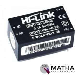

AC-DC Power Module HLK-PM12 230V to 12V /3W
- Rated input voltage: AC 100V -230V
- Input voltage range: 90V -264V AC
- Maximum input current: <0.2A
- Input current surge: <10A
- Maximum input voltage: <270V AC
- Input Low Voltage Efficiency Vin=110V AC,Output full-load≥ 69%
- Input High Voltage Efficiency Vin=220V AC,output full-load≥ 70 %
- Short-term maximum output current: ≥1000 mA
- Long-term reliability
- Voltage Regulation: ±0.2%
- Load Regulation: ±0.5%
- Ultra-thin and small module
- High efficiency, high power density
- Low ripple and low noise
- Output overload and short circuit protection
- Working temperature: – 20 degrees to +60 degrees Celsius
- Storage temperature: -40 degrees to 80 degrees Celsius
- Relative humidity: 5-95%
- Cooling way: Natural cooling
- Atmospheric pressure: 80-106Kpa
- Weight: 21g
- Size: 38x23x18mm


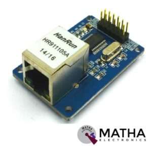
ENC28J60 ETHERNET MODULE
- ENC28J6 Ethernet chips, SOP28 package
- Operating voltage: 3.1V to 3.6V (3.3 V typical)
- Operating temperature: -40 degree to +85 degree Celsius
- IEEE 802.3 compatible Ethernet controller
- Buffer size: 8Kb
- Supports full and half-duplex mode
- SPI interface with a clock speeds up to 20MHz
- Programmable automatic rejection of erroneous packets
- Programmable automatic retransmit on a collision
- Programmable padding and CRC generation
- 25 MHz crystal oscillator
- Clock out the pin with a programmable presale
- Ethernet LAN module for Arduino/AVR/LPC/STM3
- 5V tolerant inputs
- SPI interface
- Led power indicator
- Dimension: 58*34*17mm


IRF520 MOSFET DRIVER MODULE SENSOR
- Operating Voltage: 3.3v & 5v
- Digital level port
- Output load voltage: 0-24v
- Output load current: <5A
- The heat sink is added for currently more than 1A
- Compatible with Arduino, MCU, ARM, Raspberry pi
- PWM dimming LED used to step-less dimming, variable-speed motor
- Output PWM can be adjusted by the original IFR520 MOS
- Arduino can drive up to 24V, such as led lights, dc motors, miniature pumps, solenoid valves etc.
- Dimension:34*30*18mm
- Size: 10gm
Reviews
There are no reviews yet.