
I am text block. Click edit button to change this text. Lorem ipsum dolor sit amet, consectetur adipiscing elit. Ut elit tellus, luctus nec ullamcorper mattis, pulvinar dapibus leo.
Sold out


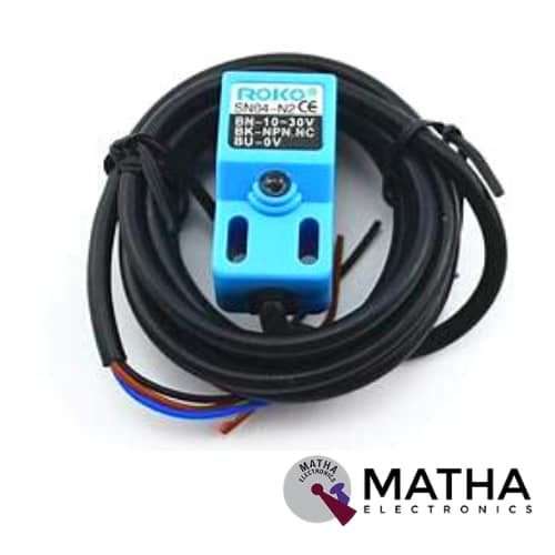
RIKO SN04-N NPN Inductive Proximity Sensor
Original price was: ₹635.00.₹600.00Current price is: ₹600.00. inc. GST
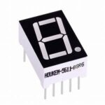
1 Digit 7 Segment Display Common Cathode
₹20.00 inc. GST
KY-036 Metal Touch Sensor Module
- Main chip: LM393
- Working voltage: for DC 5V
- Single-channel signal output
- Low-level output signal used for human body touch sensor alarm
- Adjustable sensitivity
- Pin Connector to board: 4 Pins
- Dimensions: 43 x 16 x 15 mm / 1.69 x 0.63 x 0.59 inch
- Single-channel signal output
- Low-level output signal used for human body touch sensor alarm
- Adjustable sensitivity
- Long life
- High reliability
Description
This KY-036 Metal Touch Sensor Module is designed as a touch sensor (MOSFET) that generates an output when the metal leg of the MOSFET is touched and fed to the LM386 amplifier. The amplifier further transmits the data to the analogue output pin of the module. We then connect this to an Arduino analogue input pin. KY-036 comes with four pins within the Sensor Module. They are VCC, GND, Analog output, Digital output. The KY-036 Touch Sensor Module make use of a floating lead on a Darlington transistor to detect a touch. The two onboard are present in the module in which red LED lights when power is applied. A green or red LED lights when a touch is detected.
In this Touch Metal Detector, the VCC of the module is connected to +5v of Arduino and GND of the module to Arduino Ground. Afterwards, connect the Digital output of the module to pin 8 of Arduino and the Analog output pin of the module to analogue pin A0 of Arduino. Under this condition, when a target is detected, the metal detector produces an audible response, like a beep or change in tone. Basically, the device gives some indication of distance; which implies the closer the metal is, the upper the tone within the earphone or the higher the needle goes.
The sensor comprises 3 main components on its circuit board. The sensor unit present at the front of the module measures the area physically. And transmits an analogue signal to the second unit, the amplifier. According to the resistant value of the potentiometer, the amplifier amplifies the signal. And sends the signal to the analogue output of the module. The third component is a comparator that switches the digital out and the LED if the signal falls under a specific value. The onboard potentiometer is used to adjust the sensitivity of the sensor.
Reviews (0)
Shipping & Delivery

Related products


2 CHANNEL 5V RELAY
- High current relay
- Two LED S to indicate relays ON/OFF status
- Low-level trigger expansion board
- Opto isolation circuitry
- Works with logic level signal 3.3V or 5V devices
- Can be used as normally open (NO) or normally closed (NC)
- Back EMF protection
- Ensures diode current protection
- AC control voltage: 250v @mx10A
- DC control voltage: 30V @max 10A
- Easy installation and fixing

4*4 MATRIX KEYPAD
The maximum voltage across each button: 24v
- The maximum current across each button: 3mA
- Easy communication with any microcontroller
- Ultra-thin design
- Adhesive backing provides easy integration
- High price-performance ratio
- Allows microcontroller to scan 8 output pins to check which 16 button
- Long life
- Maximum operating temperature: 0 degrees to 50 degrees Celsius
- Dimension: 70*77*1mm
- Weight: 7.5gm
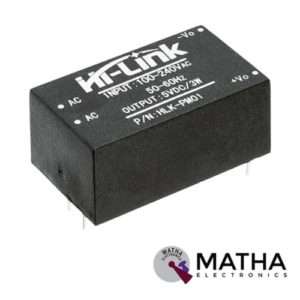
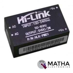
AC-DC Power Module HLK-PM01 230V to 5V /3W
- Meet UL, CE requirements
- Rated input voltage: AC 100V -230V
- Maximum input voltage: <270V AC
- Voltage Regulation: ±0.2%
- Load Regulation: ±0.5%
- High efficiency, high power density
- Ultra-thin and small module
- Low ripple and low noise
- Output overload and short circuit protection
- 100% load ageing and testing
- The product is designed to meet the requirements of the EMC and Safety Test
- Low power consumption, environmental protection, no-load loss <0.1W
- High efficiency, high power density
- Working temperature: – 20 degrees to +60 degrees Celsius
- Storage temperature: + 80-40 -degree
- Relative humidity: 5-95%
- Cooling way: Natural cooling
- Atmospheric pressure: 80-106Kpa
- Weight: 21g
- Size: 38x23x18mm


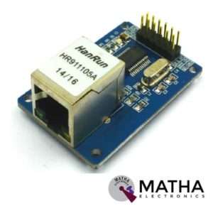
ENC28J60 ETHERNET MODULE
- ENC28J6 Ethernet chips, SOP28 package
- Operating voltage: 3.1V to 3.6V (3.3 V typical)
- Operating temperature: -40 degree to +85 degree Celsius
- IEEE 802.3 compatible Ethernet controller
- Buffer size: 8Kb
- Supports full and half-duplex mode
- SPI interface with a clock speeds up to 20MHz
- Programmable automatic rejection of erroneous packets
- Programmable automatic retransmit on a collision
- Programmable padding and CRC generation
- 25 MHz crystal oscillator
- Clock out the pin with a programmable presale
- Ethernet LAN module for Arduino/AVR/LPC/STM3
- 5V tolerant inputs
- SPI interface
- Led power indicator
- Dimension: 58*34*17mm


IRF520 MOSFET DRIVER MODULE SENSOR
- Operating Voltage: 3.3v & 5v
- Digital level port
- Output load voltage: 0-24v
- Output load current: <5A
- The heat sink is added for currently more than 1A
- Compatible with Arduino, MCU, ARM, Raspberry pi
- PWM dimming LED used to step-less dimming, variable-speed motor
- Output PWM can be adjusted by the original IFR520 MOS
- Arduino can drive up to 24V, such as led lights, dc motors, miniature pumps, solenoid valves etc.
- Dimension:34*30*18mm
- Size: 10gm


Red TTP223 Touch button Module
- Input Voltage: 2 Volt - 5.5 Volts DC.
- Current Consumption: < 7 µA
- Low Power Mode and Fast Mode
- Start-up Calibration Delay: 0.5 Sec
- Simple, easy to use, with Auto Calibration
- Output mode is set by Jumper
- The response time max is ~ 60mS in fast mode, ~220mS at low power mode @VDD=3V.
- Sensitivity can adjust by the capacitance (0~50pF).
- Supports momentary or latching/toggle modes.
- Have two kinds of sampling length by pad option (SLRFTB pin)
- Provides Fast mode and Low Power mode selection by pad option (LPMB pin).
- Provides direct mode toggle mode by pad option (TOG pin).
- All output modes can be selected as active high or active low by pad option (AHLB pin).
- Have the maximum on-time 100sec by pad option (MOTB pin).
- Have external power-on reset pin (RST pin).
- Auto-calibration &Re-calibration period is about 4.0 sec when the key has not to be touched.
- Dimensions: 15mm x 11mm.
Reviews
There are no reviews yet.