
I am text block. Click edit button to change this text. Lorem ipsum dolor sit amet, consectetur adipiscing elit. Ut elit tellus, luctus nec ullamcorper mattis, pulvinar dapibus leo.
Sold out

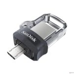
SanDisk Ultra Dual 32GB USB 3.0 OTG Pen Drive
Original price was: ₹560.00.₹550.00Current price is: ₹550.00. inc. GST
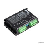
Leadshine DM542
₹4,500.00 inc. GST
Leadshine DM320C
₹5,500.00 inc. GST
- Supply voltage up to +30 VDC
- Output current programmable, from 0.3A to 2.0A
- Pulse input frequency up to 70 kHz
- TTL compatible and optically isolated input
- Automatic idle-current reduction
- Suitable for 2-phase and 4-phase motors
- Support PUL/DIR and CW/CCW modes
- Over-voltage, over-current, phase-error protection
- Anti-Resonance provides optimum torque and nulls mid-range instability
- Self-test and Auto-configuration technology offers optimum responses with different motors
- Microstep resolutions programmable, from full-step to 102,400 steps/rev
- Support PUL/DIR and CW/CCW modes
- Over-voltage, over-current, phase-error protection
- Its unique features make the DM320C an ideal solution for applications that require low-speed smoothness
Out of stock
Description
DM320C is defined as a versatile fully digital stepping driver designed based on a DSP with an advanced control algorithm. This next generation of digital stepping motor controls offers a unique level of system smoothness. Thereby providing optimum torque and nulls mid-range instability. It features motor self-test and parameter auto-setup technology providing optimum responses while using different motors and is easy to use.
The DM320C supports PUL/DIR and CW/CCW modes and pulse active at rising or falling edges. It also uses optocouplers to increase noise immunity and interface flexibility. In case If the optocouplers’ supply voltage is greater than +5V, a current-limiting resistor is connected at each command signal terminal to prevent overheating the optocouplers. The onboard RED LED indicate protection activated status.
The DM320C can drive any 2-phase and 4-phase hybrid stepping motors. Therefore, in order to improve reliability, the driver features some built-in protection functions such as Over-current Protection, Over-voltage Protection, and phase error protection. When the continuous current exceeds 3Amp or in case of a short circuit between motor coils or between motor coil and ground, Over-current protection activates and RED LED turns on. In case when the power supply voltage exceeds 30 VDC, over current protection is activated and the RED LED will turn on. Phase error protection comes into the function when Motor power lines are wrong & not connected will activate this protection. In short, compared to the DM422C, the DM320C is more compact and lower cost.
DM320C operates with much smaller noise, lower heating, smoother movement than most of the drivers. This unique feature makes it an ideal solution for applications that require low-speed smoothness.
Reviews (0)
Shipping & Delivery

Related products

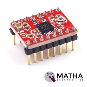
A4988 Stepper Motor
- Operating voltage supply: 8 V to 35 V
- Continuous current per phase: 1 Amp
- Maximum current per phase: 2 Amp
- Minimum logic voltage: 3V
- Maximum logic voltage: 5.5V
- Microstep resolutions: Full, 1/2, 1/4, 1/8, and 1/16
- Logic Voltage supply: 3.3 V to 5 V
- Compatible with 3V3 and 5V microcontrollers
- Our Board comes with 0.1 Ohm Sensor resistors
- Five different step resolutions: full-step, half-step, quarter-step, eighth-step, and sixteenth-step
- The Correct current decay mode (fast decay or slow decay) is selected by chopping the control
- Over-temperature thermal shutdown, under-voltage lockout, and crossover-current protection
- Short-to-ground and shorted-load protection
- 4-layer, 2 oz copper PCB for improved heat dissipation
- Exposed solderable ground pad below the driver IC on the bottom of the PCB

Bullet Connector 3.5MM
- Diameter: 3.5mm
- Length:1.5CM & 1.5CM
- Amperage Rating: 60A -180Amps
- Hook up RC Battery to Electronic
- Hook up Brushless motor to electronic speed control
- These have low resistance and gives the best electric flow
- 5mm gold connectors Male
- 5mm gold connectors Female
- Dimension: 2.7*2.1*3inch
- Weight: 67gm
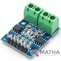
L9110 DC Stepper Motor Driver Board H-Bridge
- Low static work current
- Power supply voltage: DC2.5-12V
- Each channel has 800mA continuous current output
- Low saturation pressure drop
- TTL/CMOS output level compatible can be connected directly to the CPU
- Output built-in clamping diode, apply to the perceptual load
- Control and drive integrated into IC
- Have pin high-pressure protection function
- Working temperature: 0-80 °C
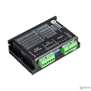
Leadshine DM542
- Good high-speed performance
- Supply voltage up to +50VDC
- Output current up to 4.2A
- Pulse frequency up to 300 KHz
- Extremely cost-effective
- Automatic idle-current reduction
- 3-state current control technology
- Self-adjustment technology
- Pure-sinusoidal current control technology
- TTL compatible and optically isolated input
- 15 selectable resolutions in decimal and binary, up to 25,600 steps/rev
- Suitable for 2-phase and 4-phase motors
- DIP switch current setting with 8 different values
- Support PUL/DIR and CW/CCW modes
- Short-voltage, over-voltage, over-current protection


MACH3 interface board
- Compatible Stepper Motor Driver - Max 5 2-phase Microstep controllers
- Driver type - Pulse and Direction signal control
- Wide input voltage range: 12-24V, and with anti-reverse function.
- Output 0-10V analogue voltage for the inverter to control the spindle speed.
- Compatible with MACH3, Linux CNC (EMC2) etc. parallel-control CNC software.
- USB power supply and peripherals power phase are separate to protect computer security.
- All the signals are to-isolate which can protect your computer security.
- 5-input interface to define the Limit, Emergence-Stop, Cutter alignment, etc.
- Wide input voltage range: 12-24V, and with anti-reverse function.
- One relay output control interface, accessed by the spindle motor or the air pump, water pump, etc.
- Maximum support 5-axis stepper motor driver controllers
- Output 0-10V analogue voltage for the inverter to control the spindle speed.
- All the way to the relay output port, control spindle switch. Output port P17 mouth.
- One relay output control interface, accessed by the spindle motor or the air pump, water pump, etc.
- Weight - Approx. 75g
- Dimensions - 90 * 70 * 20mm
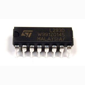
Motor Driver IC – L293D
- Can be used to run Two DC motors with the same IC.
- Speed and Direction control is possible
- Motor voltage Vcc2 (Vs): 4.5V to 36V
- Maximum Peak motor current: 1.2A
- Maximum Continuous Motor Current: 600mA
- Supply Voltage to Vcc1(vss): 4.5V to 7V
- Transition time: 300ns (at 5Vand 24V)
- Automatic Thermal shutdown is available
- Available in 16-pin DIP, TSSOP, SOIC packages
- Featuring Unit rode L293 and L293D
- Wide Supply-Voltage Range: 4.5 V to 36 V
- Separate Input-Logic Supply
- Internal ESD Protection
- Thermal Shutdown
- High-Noise-Immunity Inputs
- Output Current 1 A Per Channel (600 mA for L293D)
- Peak Output Current 2 A Per Channel (1.2 A for L293D)
- Output Clamp Diodes for Inductive Transient Suppression

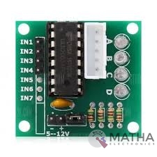
ULN2003 Driver
- Contains 7 high-voltage and high current Darlington pairs
- Each pair is rated for 50V and 500mA
- Input pins can be triggered by +5V
- All seven Output pins can be connected to gather to drive loads up to (7×500mA) ~3.5A.
- Can be directly controlled by logic devices like Digital Gates PIC etc
- Available in 16-pin DIP, TSSOP, SOIC packages
- Dimensions: 32 x 18 x 11mm (LxWxH)
- Weight: 3 gm
Reviews
There are no reviews yet.