
I am text block. Click edit button to change this text. Lorem ipsum dolor sit amet, consectetur adipiscing elit. Ut elit tellus, luctus nec ullamcorper mattis, pulvinar dapibus leo.
-5%Sold out
Wemos D1 Mini ESP8266 NodeMCU WIFI board for Arduino
Original price was: ₹400.00.₹350.00Current price is: ₹350.00. inc. GST
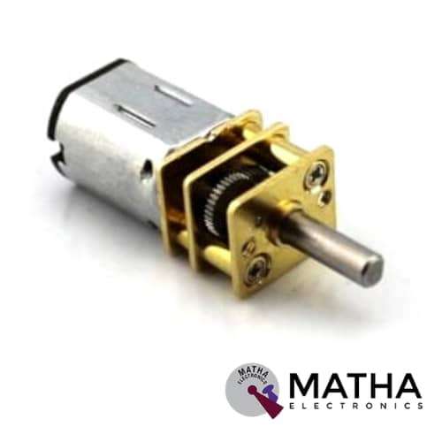
N20 Model - 40 RPM DC 12V Torque Gearbox Micro Gear Box Motor
Original price was: ₹400.00.₹350.00Current price is: ₹350.00. inc. GST
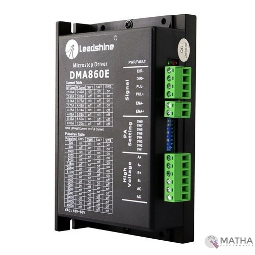
Leadshine DMA860E Stepper Motor Driver
Original price was: ₹6,000.00.₹5,700.00Current price is: ₹5,700.00. inc. GST
- Model: DMA860E.
- Control Mode: Step & Direction.
- Max Input Frequency: 200 kHz.
- Input Voltage Range: 18 – 80 VAC / 24 – 110 VDC.
- Suggested Power Supply Voltage Range: 36-90 VDC /24-60 VAC.
- Number of DIP Switch Resolution Configurations: 16.
- 16 selectable micro-step resolutions of 400-51,200 via DIP switches.
- 8 selectable output current settings of 2.4 – 7.2A via DIP switches.
- Logic Current Range: 7-16mA (10mA typical).
- Logic Voltage Range: 4-5 VDC for pulse active high (default), or 0-0.5V for pulse active low.
- Pulse enabled at: Rising edge.
- Idle Current Percentage: 50 %.
- Number of Digital Inputs: 3.
- Step Width: 2,500 ns.
- Minimal Direction Setup Time: 5,000 ns.
- Isolation Resistance: 500M Ohm..
- Ambient Temperature: 0-50°C.
- Humidity: 40–95% RH.
- Operating Temperature: 0-70°C.
- Vibration: 5.9 m/s2 Max.
- Motor auto-identification and parameter auto-configuration for optimal torque from wide-range motors.
- Step & direction (PUL/DIR) and CW/CCW (via internal jumper set) control. Step & direction by default Multi-Stepping for smooth motor movement.
- Opto Isolation for input control signals.
- Soft-start with no “jump” when powered on.
- Protections for over-voltage and over-current.
- Dimension: 5.94 X 3.82 X 2.24 Inches.
- Weight: 1.13 lbs.
Out of stock
Description
DMA860E defined as a versatile fully digital stepping driver designed based on a DSP with an advanced control algorithm. By implementing Leadshine advanced stepper control technology, this stepper motor is capable of driving 2-phase and 4 phase stepper motors. This next generation of digital stepping motor controls offers a unique level of system smoothness. Thereby providing optimum torque and nulls mid-range instability. It features motor self-test and parameter auto-setup technology providing optimum responses while using different motors and is easy-to-use.
The DMA860E supports PUL/DIR and CW/CCW modes and pulse active at rising or falling edge. It also uses optocouplers to increase noise immunity and interface flexibility. In case If the optocouplers’ supply voltage greater than +5V, a current-limiting resistor connected at each command signal terminal to prevent overheating the optocouplers. The on-board RED LED indicates protection activated status. In order to improve reliability, the driver features some built-in protection functions such as Over-current Protection, Over-voltage Protection.
DMA860E operates with much smaller noise, lower heating, smoother movement than most of the drivers. The DMA860E operates at a voltage range of 18-80VAC or 24-110VDC and it can output up to 7.2A current. Here all the micro-step and output current are performed via DIP switches. This driver offers a wide range of applications in the field such as X-Y tables, engraving machines, labeling machines, laser cutters, pick and place devices, etc. Therefore, these are the perfect solution for applications requiring simple step & direction control of NEMA 23, 24, 34, and 42 stepper motors.
Reviews (0)
Shipping & Delivery

Related products

“PWM Generator Module for Stepper Motor Driver with Forward and Reverse Function “
- Board can be used to generate PWM signals for the stepper motor driver
- Operating Voltage: 12VDC
- Three Frequency Range
- Forward and Reverse Function.
- It has three frequency ranges selectable via onboard jumpers.
- Frequency can be measured via PUL and common cathode (GND) ports.
- The board has two sets of power input

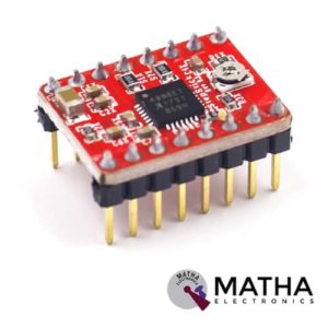
A4988 Stepper Motor
- Operating voltage supply: 8 V to 35 V
- Continuous current per phase: 1 Amp
- Maximum current per phase: 2 Amp
- Minimum logic voltage: 3V
- Maximum logic voltage: 5.5V
- Microstep resolutions: Full, 1/2, 1/4, 1/8, and 1/16
- Logic Voltage supply: 3.3 V to 5 V
- Compatible with 3V3 and 5V microcontrollers
- Our Board comes with 0.1 Ohm Sensor resistors
- Five different step resolutions: full-step, half-step, quarter-step, eighth-step, and sixteenth-step
- The Correct current decay mode (fast decay or slow decay) is selected by chopping the control
- Over-temperature thermal shutdown, under-voltage lockout, and crossover-current protection
- Short-to-ground and shorted-load protection
- 4-layer, 2 oz copper PCB for improved heat dissipation
- Exposed solderable ground pad below the driver IC on the bottom of the PCB


DM556 Digital Stepper Motor Driver with Micro Stepping 20 to 50V 5.6A
- Good high-speed performance
- Supply voltage: +50VDC
- Output current from 0.5A to 5.6A
- Pulse input frequency up to 200 kHz
- Extremely cost-effective
- Automatic idle-current reduction
- Self-test and Auto-configuration technology TTL compatible and optically isolated input
- Micro step resolutions programmable, from full-step to 102,400 steps/rev
- Suitable for 2-phase and 4-phase motors
- Support PUL/DIR and CW/CCW modes
- Anti-Resonance provides optimum torque and nulls mid-range instability
- Extra-low motor noise offers excellent quietness
- Over-voltage, over-current protection and phase error protection


IRF520 MOSFET DRIVER MODULE SENSOR
- Operating Voltage: 3.3v & 5v
- Digital level port
- Output load voltage: 0-24v
- Output load current: <5A
- The heat sink is added for currently more than 1A
- Compatible with Arduino, MCU, ARM, Raspberry pi
- PWM dimming LED used to step-less dimming, variable-speed motor
- Output PWM can be adjusted by the original IFR520 MOS
- Arduino can drive up to 24V, such as led lights, dc motors, miniature pumps, solenoid valves etc.
- Dimension:34*30*18mm
- Size: 10gm


L293D Motor Driver Shield
- L293D motor driver chip & 74HC595 shift register
- Four H-bridges
- Terminal blocks and jumper to connect external power, for separate logic/motor supplies
- Up to 4 bi-directional DC motors with individual 8-bit speed selection
- Up to 2 stepper motors (unipolar or bipolar) with single coil, double coil or interleaved stepping.
- 2 connections for 5V ‘hobby’ servos connected to the Arduino’s high-resolution dedicated timer
- 4 H-Bridges: L293D chipset provides 0.6A per bridge (1.2A peak) with thermal shutdown protection, internal kickback protection diodes. Can run motors on 4.5VDC to 25VDC.
- Pull-down resistors keep motors disabled during power-up
- Big terminal block connectors to easily hook up wires (18-26AWG) and power
- Arduino reset button brought up top
- Tested compatible with Arduino Mega 1280 & 2560, Diecimila, Duemilanove, and UNO
- PCB Size: 69 x 53 mm


L298P Motor Shield motor driver
- L298P based Arduino motor driver shield
- Operating Voltage 5V to 12V
- Motor controller L298P, Drives 2 DC motors or 1 stepper motor
- The logical part of the input voltage VD: 5V
- Driven part of the input voltage VS: VIN Input 6.5 ~ 12V, PWRIN 4.8 ~ 35V input
- The logical part of the work current Iss:<36mA
- Driven part of the operating current Io:<2A
- Current sensing 1.65V/A
- Free running stop and brake function
- Maximum power dissipation: 25W (T = 75 Celsius)
- Max current 2A per channel or 4A max (with external power supply)
- Control signal input level: High 2.3V
- Onboard Bluetooth interface, you can directly plug, no wiring required.
- The board with L298P motor drive chip, directly with the motherboard digital I/O port (D10, D11, D12, D13), without cumbersome wiring.
- Onboard buzzer (D4), you can set the reverse alarm ringtones.
- D2, D3, D5, D6, D7, D9 are not occupied by the digital interface.
- A 0 – A 5 six analogue interfaces.
- Forward and Backward steering are indicators


MACH3 interface board
- Compatible Stepper Motor Driver - Max 5 2-phase Microstep controllers
- Driver type - Pulse and Direction signal control
- Wide input voltage range: 12-24V, and with anti-reverse function.
- Output 0-10V analogue voltage for the inverter to control the spindle speed.
- Compatible with MACH3, Linux CNC (EMC2) etc. parallel-control CNC software.
- USB power supply and peripherals power phase are separate to protect computer security.
- All the signals are to-isolate which can protect your computer security.
- 5-input interface to define the Limit, Emergence-Stop, Cutter alignment, etc.
- Wide input voltage range: 12-24V, and with anti-reverse function.
- One relay output control interface, accessed by the spindle motor or the air pump, water pump, etc.
- Maximum support 5-axis stepper motor driver controllers
- Output 0-10V analogue voltage for the inverter to control the spindle speed.
- All the way to the relay output port, control spindle switch. Output port P17 mouth.
- One relay output control interface, accessed by the spindle motor or the air pump, water pump, etc.
- Weight - Approx. 75g
- Dimensions - 90 * 70 * 20mm
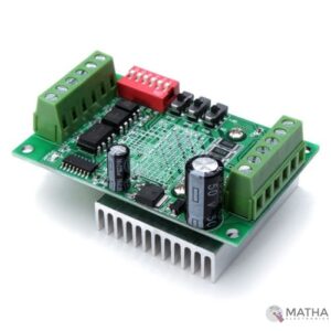
TB6560 Driver Board 3A CNC Router Single 1 Axis Controller Stepper Motor
- Supply voltage up to +32 VDC
- Output current up to 3.0A
- Pulse frequency up to 20 KHz
- Suitable for 2-phase and 4-phase motors
- Over-voltage and short-circuit protection
- 7 output current choices, max 3200 steps/rev
- Automatic idle-current reduction
- Single-chip motor driver for sinusoidal micro-step control of stepping motors
- High output withstands voltage due to the use of BiCD process:
- Forward and reverse rotation
- Selectable phase excitation modes (2, 1-2, 2W1-2, and 4W1-2)
- High output withstand voltage: VDSS = 40 V
- High output current: IOUT = TB6560AHQ: 3.5 A (peak)
- Internal pull-down resistors on inputs: 100 kΩ
- Output monitor pin: MO current (IMO (max) = 1 mA)
- Reset and enable pins
Reviews
There are no reviews yet.