
I am text block. Click edit button to change this text. Lorem ipsum dolor sit amet, consectetur adipiscing elit. Ut elit tellus, luctus nec ullamcorper mattis, pulvinar dapibus leo.
-17%Sold out

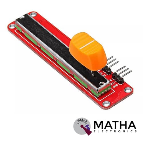
Double Analog Potentiometer Module With Slide Potentiometer Slip Adjustable Resistance For Arduino
Original price was: ₹300.00.₹250.00Current price is: ₹250.00. inc. GST
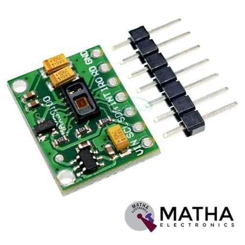
MAX30102 Heart Rate Oxygen Pulse Breakout Sensor Module For Arduino
Original price was: ₹500.00.₹450.00Current price is: ₹450.00. inc. GST
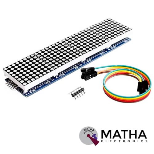
MAX7219 Dot Led Matrix Module 4 In 1 Display with 5P Line Module For Arduino Micro-controller
Original price was: ₹900.00.₹750.00Current price is: ₹750.00. inc. GST
- Driver Chip: MAX7219
- Input Voltage: 3.7 to 5.3 V
- Input Current: 320 mA
- Requires only 3 communication wires of MCU
- Pre-cascaded MAX7219 Dot Matrix LED Module.
- The overall size of the display is very compact
- With 64 fixing screw holes, hole diameter: 3mm.
- M3 holes for mounting.
- Module with input and output interfaces
- Support for cascading multiple modules
- Quite large display
- Display Dimensions: 32x32x6 mm
- PCD Dimensions: 128×32mm
- Weight: 55 gm
Out of stock
Description
This Dot Led Matrix Module incorporates the MAX7219 Driver chip designed based on an integrated serial input/output common-cathode display driver. This module interface with MPU to 7 segments LED display. This LED display is of up to 8 digits, bar-graph displays, or 64 individual LEDs. Max7219 consists of an on-chip BCD code decoder, multiplex scan circuitry, segment digits drivers, and an 8*8 static RAM. Hence, offers a slew rate, limited segment drivers, to reduce EMI. It requires only one external register to set the segment current of each LED.
The individual module features 8×8 LED’s, each controlled precisely by the MAX7219 driver to generate the colour pattern you wish. The great advantage of using this is users will have control over all of the 64 LED by just connecting 3 output communication wires to microcontrollers like Arduino etc. Thus all common micro-controllers communicate easily to this module by using a 4-wire serial interface. Each output can be addressed without refreshing the entire display. Using 3 I/O lines for driving the display, making it ideal for your microcontroller projects. Moreover, these 4 Dot Matrix LED’s cascaded to form a single LED Display to allot more area to the user on the display. Therefore, by simply connecting the output pins of the previous breakout board to the input pins of the new module, it is possible to connect as many DOT LED Modules to the Arduino.
Wiring Instructions:-
- Connect the left side of the module to the input port, the right to an output port.
- When the control of a single module, simply input port connected to CPU
- In cascaded modules, input and output termination CPU, an output terminal of the first module connected to the input terminal of the second module, the first two modules of the input terminal of the three termination modules, and so on.
Reviews (0)
Shipping & Delivery

Related products


10D OF 9-AXIS GY-87
- Power supply: DC 3.3V TO 5V
- 3 Axis Gyro+ Acceleration+ Magnetic field
- Air pressure module
- Inbuilt ultra-low noise linear LDO voltage regulator
- Inbuilt onboard filters. which reduce noise from motor and another high current
- Communication: I2C protocol
- Power LED
- Designed for 5V logic
- Can easily select two I2C addresses for MPU6050 by soldered jumper
- Dimension: 2.2*1.7cm
- Size: 6gm


2 CHANNEL 5V RELAY
- High current relay
- Two LED S to indicate relays ON/OFF status
- Low-level trigger expansion board
- Opto isolation circuitry
- Works with logic level signal 3.3V or 5V devices
- Can be used as normally open (NO) or normally closed (NC)
- Back EMF protection
- Ensures diode current protection
- AC control voltage: 250v @mx10A
- DC control voltage: 30V @max 10A
- Easy installation and fixing
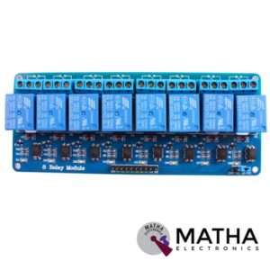
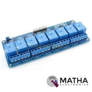
8 CHANNEL 5V RELAY
- Relay operating voltage: 5V
- 8 channel
- High impedance controller pin
- One normally closed contact and one normally opened
- Useful for appliances control
- Power supply indicator and control indicator lamp
- Pull-down circuit to avoid malfunction
- Can control both DC and AC to 220v AC load
- Works with both 3.3 V and 5 V logic with the less current drive
- 3 terminals per SPDT relay
- Standard interface can be directly controlled by a microcontroller like Arduino, 8051, AVR, PIC, DSP, ARM, MSP430, TTL logic
- Dimension: 7*6.4*1 inch


I2C MODULE WITH 16*2 CHARACTER LCD
- Supply voltage: 5V
- Display mode: STN
- Display format: 16*2
- Input data: 4 bit or 8 bit (for LCD)
- I2C address: 0x20~0x27 (original address is 0x20,we can change it ourselves)
- Compatible with multiple communication logic levels: 2.8~5VDC
- Compatible for 16*2 LCD
- Serial I2C control of LCD display using PCF8574
- Allow data display via only 2 wires.
- Backlight and contrast adjustment by the potentiometer
- Supports 7 ASCII fonts, 5 graphic functions
- Supports 128 level backlight lightness adjustment.
- Support 64 level screen contrast adjustment
- Supports device address modification
- Dimension: 10*4*5cm
- Size: 150gm


IRF520 MOSFET DRIVER MODULE SENSOR
- Operating Voltage: 3.3v & 5v
- Digital level port
- Output load voltage: 0-24v
- Output load current: <5A
- The heat sink is added for currently more than 1A
- Compatible with Arduino, MCU, ARM, Raspberry pi
- PWM dimming LED used to step-less dimming, variable-speed motor
- Output PWM can be adjusted by the original IFR520 MOS
- Arduino can drive up to 24V, such as led lights, dc motors, miniature pumps, solenoid valves etc.
- Dimension:34*30*18mm
- Size: 10gm
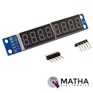
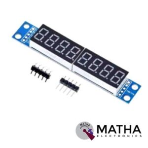
MAX7219 led module 8 digit 7 segment display
- Power: 5V
- Colour: Red/Blue (This colour means the colour of the board, not the LED)
- Material: PCB + Electronic Components
- MAX7219 digital display control module
- This module is compatible with 5V and 3.3V microcontrollers.
- You can use it for Arduino
- Only three IO ports are used to drive the eight-digit display. MAX7219 supports flicker-free displays as well as cascading displays.
Reviews
There are no reviews yet.