
I am text block. Click edit button to change this text. Lorem ipsum dolor sit amet, consectetur adipiscing elit. Ut elit tellus, luctus nec ullamcorper mattis, pulvinar dapibus leo.
-27%Sold out
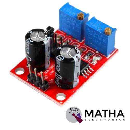
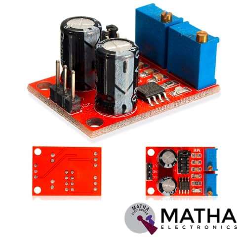
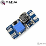
MT3608 2A MAX DC-DC STEP UP POWER MODULE BOOSTER
Original price was: ₹200.00.₹150.00Current price is: ₹150.00. inc. GST
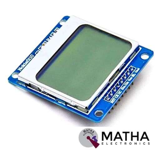
NOKIA DISPLAY MODULE
Original price was: ₹550.00.₹399.00Current price is: ₹399.00. inc. GST
NE555 PULSE FREQUENCY ADJUSTABLE MODULE
Original price was: ₹184.00.₹135.00Current price is: ₹135.00. inc. GST
- Input voltage: DC 5V-15V
- Output amplitude: 4.2V V-PP to 11.4V V-PP
- Input current: 100mA
- Output current: 15mA for 5v & 35 mA for 12v
- 50% duty cycle form 3.7hz(minimum)
- 98% duty cycle for 1.3 KHz(max)
- Output LED indication
- Generate adjustable pulse for MCU
- Generate adjustable pulse to control circuitry
- Dimension: 31*22*2mm
Out of stock
Description
NE555 pulse frequency duty cycle adjustable module is a 5V square wave signal generator. This module is based on NE555 Timer IC. The output frequency level is adjustable. The module is powered from a power supply range of 4.5v to 12v.NE555 pulse frequency adjustable module square wave generator produces a continuous square wave output between 15 Hz to 24 kHz. The duty cycle and frequency are not separately adjustable, adjusting the duty cycle will change the frequency.
The output frequency and duty cycle are adjusted using the following variables:
Period T = 0.7 (RA +2 RB) C
RA, RB are 0-10K Ohm adjustable potentiometers
1Hz ~ 50Hz: C = 0.001UF
50Hz ~ 1kHz: C = 0.1UF
1KHz ~ 10kHz: C = 1UF
10kHz ~ 200kHz: C = 100UF
As a result, the NE555 acts as an astable multivibrator, generating pulses between 4 HZ and 1.3 kHz. A ten-turn frequency adjustment control is provided by the module. Because the NE555 has an inbuilt resistor that can be modified, the output frequency can be altered. The square wave output is controlled via a multi-turn potentiometer on board. To simply alter the output wave, there are four jumpers and two variable resistors. As a consequence, it is employed to operate the stepper motor for creating the square wave driving signal.
The NE555 timer IC is a multi-purpose integrated circuit that may be used as a timer, pulse generator, or oscillator. As a consequence, adjustable power generation modules are used in microcontrollers and adjustable pulse control-related circuits. The output of the square waveform is indicated via the LED. The low level indicates that the LED is turned on, while the high level indicates that it is turned off. The 555 was introduced by Signetics in 1971 and is still widely used because to its ease of use, low price, and stability. Many firms also produce the 555 in both bipolar and low-power CMOS versions.
Reviews (0)
Shipping & Delivery

Related products

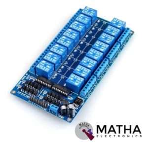
16 CHANNEL 12V RELAY
- 16 channel 12V relay board
- Operating voltage: 12V
- Supply current: 0.2 A
- Relay contact current capacity of 10A @250 V AC/10A@ 30V AC
- Optocoupler protection
- LED status indicates relay ON/OFF state.
- The 10-16 road can be any full-on/off or any road
- Common terminal(com) in each rely is user friendly and can be accessed by different signal
- Normally closed or normally open with each port
- Strong anti-jamming ability and stable performance
- The on-board power supply module doesn’t need any external power
- Dimension: 180*90*20mm
- Weight: 100gm


4*3 MATRIX KEYPAD
- Operating voltage: 12V DC
- The maximum voltage across each button: 24v
- The maximum current across each button: 3mA
- Ultra-thin design
- Adhesive backing provides easy integration
- Easy communication with any microcontroller
- Flexible
- Only 7 microcontroller pins required to access 12 keys
- High price-performance ratio
- Allows microcontroller to scan 8 output pins to check which 16 button
- Long life
- Maximum operating temperature: 0 degrees to 50 degrees Celsius
- Dimension: 70*77*1mm
- Weight: 7.5gm
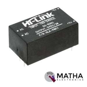
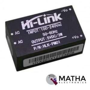
AC-DC Power Module HLK-PM01 230V to 5V /3W
- Meet UL, CE requirements
- Rated input voltage: AC 100V -230V
- Maximum input voltage: <270V AC
- Voltage Regulation: ±0.2%
- Load Regulation: ±0.5%
- High efficiency, high power density
- Ultra-thin and small module
- Low ripple and low noise
- Output overload and short circuit protection
- 100% load ageing and testing
- The product is designed to meet the requirements of the EMC and Safety Test
- Low power consumption, environmental protection, no-load loss <0.1W
- High efficiency, high power density
- Working temperature: – 20 degrees to +60 degrees Celsius
- Storage temperature: + 80-40 -degree
- Relative humidity: 5-95%
- Cooling way: Natural cooling
- Atmospheric pressure: 80-106Kpa
- Weight: 21g
- Size: 38x23x18mm
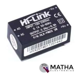

AC-DC Power Module HLK-PM03 230V to 3.3V /3W
- Meet UL, CE requirements
- Rated input voltage: AC 100V -230V
- Input voltage range: 90V -264V AC
- Maximum input current: <0.2A
- Input current surge: <10A
- Maximum input voltage: <270V AC
- Input Low Voltage Efficiency Vin=110V AC,Output full-load≥ 69%
- Input High Voltage Efficiency Vin=220V AC,output full-load≥ 70 %
- Long-term reliability
- Voltage Regulation: ±0.2%
- Load Regulation: ±0.5%
- Ultra-thin and small module
- High efficiency, high power density
- Low ripple and low noise
- Output overload and short circuit protection
- Working temperature: – 20 degrees to +60 degrees Celsius
- Storage temperature: -40 degrees to 80 degrees Celsius
- Relative humidity: 5-95%
- Cooling way: Natural cooling
- Atmospheric pressure: 80-106Kpa
- Weight: 21g
- Size: 38x23x18mm
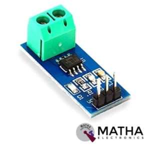

CURRENT SENSOR ACS712 30AMPS
- Current sensor chip: ACS712ELC-30A
- Supply voltage: 4.5V to 5.5V DC
- Current range: -30A to 30A
- Sensitivity: 66 millivolt/ampere
- Low noise analogue signal path
- Output rise time: 5 micro sec
- Extremely stable output offset voltage
- Zero magnetic hysteresis
- Factory trimmed for accuracy
- Easy to interface with a microcontroller, since it outputs an analogue voltage
- Onboard power indicator
- Dimension: 7*5*5cm
- Weight: 400gm


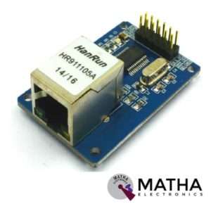
ENC28J60 ETHERNET MODULE
- ENC28J6 Ethernet chips, SOP28 package
- Operating voltage: 3.1V to 3.6V (3.3 V typical)
- Operating temperature: -40 degree to +85 degree Celsius
- IEEE 802.3 compatible Ethernet controller
- Buffer size: 8Kb
- Supports full and half-duplex mode
- SPI interface with a clock speeds up to 20MHz
- Programmable automatic rejection of erroneous packets
- Programmable automatic retransmit on a collision
- Programmable padding and CRC generation
- 25 MHz crystal oscillator
- Clock out the pin with a programmable presale
- Ethernet LAN module for Arduino/AVR/LPC/STM3
- 5V tolerant inputs
- SPI interface
- Led power indicator
- Dimension: 58*34*17mm


ISD1820 MODULE (10 SEC)
- Operating voltage: 2.6v to 5v
- Record and playback up to 10 sec
- Push-button and microcontroller controllable AGC circuit added tom increase audio playback volume
- Recording time: 8- 20 sec
- Built-in microphone
- On-chip 8-ohm speaker driver
- High quality, natural voice restored
- Available single-chip control audio recording control mode: the key to control or microcontroller, IO has drawn the line of control
- Can be used as propaganda module
- Auto power down mode
- Duration and sample rate can be extended to 20 sec by varying resistance
- Dimension: 43*34*11mm
Reviews
There are no reviews yet.