
I am text block. Click edit button to change this text. Lorem ipsum dolor sit amet, consectetur adipiscing elit. Ut elit tellus, luctus nec ullamcorper mattis, pulvinar dapibus leo.
-10%Sold out


PAM8403 DIGITAL AMPLIFIER BOARD
Original price was: ₹100.00.₹50.00Current price is: ₹50.00. inc. GST
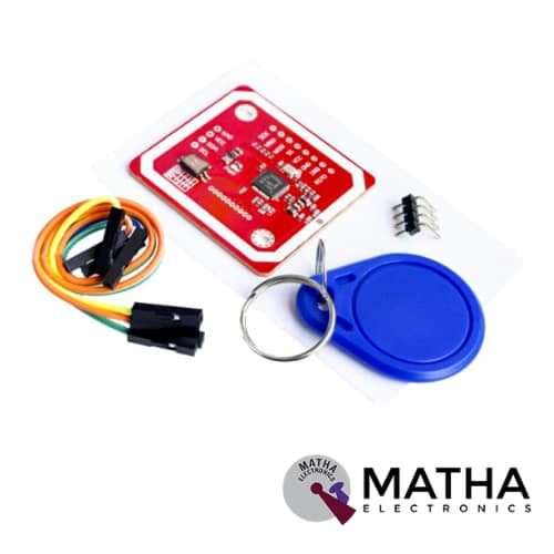
PN532 NFC MODULE
Original price was: ₹1,500.00.₹1,300.00Current price is: ₹1,300.00. inc. GST
PCF8591 ADC-DAC
Original price was: ₹500.00.₹450.00Current price is: ₹450.00. inc. GST
- Operating voltage range: 2.5V-6V
- Low standby current
- I2C bus serial input/output
- PCF8591 by 3 hardware address pins addressing
- PCF8591 I2C bus speed sampling rate decided 4 analogue inputs programmable single-ended or differential input
- Automatic incremental channel selection
- PCF8591 analogue voltage range from VSS to VDD
- On-chip track-and-hold circuit
- 8-bit successive approximation A / D converter
- 1 analogue output DAC gain
- Single power supply
- Module power supply indicator lights
- DA output indicator
- Dimension: 3.6*2.3cm
Out of stock
Description
PCF8591 ADC-DAC is a monolithically integrated, separate power supply, and low-power device. This is a breakout board with a single-chip, 8-bit CMOS data acquisition device for PCF8591 IC. The PCF8591 ADC-DAC consists of four analogue inputs and one analogue output. It communicates via a serial I2C bus interface. Three address pins A0, A1, and A2 are used in programming the hardware address. This allows the use of up to eight devices connected to the I²C‑bus without additional hardware.
Address, control, and data signals transmitted in serial via a two-wire bidirectional I2C bus. The maximum conversion rate determines the maximum speed of the I²C-bus. PCF8591 is an 8 bit analogue to digital or 8 bit digital to analogue converter module which can read analogue values up to 256. LDR and thermistor circuit is provided on the board. This indicates the precise value of light intensity and temperature of the module. There are SCL and SDA pins for serial clock and serial data address which requires 2.5-6V supply voltage. As a result, provides a low standby current in the I2C bus interface.
The knob of the potentiometer adjusts the input voltage on the module. There are also three jumpers on the board J4, J5, J6. J4 is connected to select the thermistor access circuit, J5 to select the LDR/photoresistor access circuit, and J6 to select the adjustable voltage access circuit. Two LEDs in the module indicates the output voltage intensity and the intensity of the supply voltage. So higher the output or supply voltage gives the high intensity of the LED. These LEDs can also test using a potentiometer on VCC or on an AOUT pin. PCF8591 features analogue input multiplexing, on-chip track and hold function, 8-bit analogue-to-digital conversion, and an 8‑bit digital-to-analogue conversion.
Reviews (0)
Shipping & Delivery

Related products

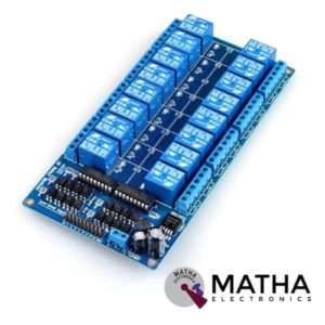
16 CHANNEL 12V RELAY
- 16 channel 12V relay board
- Operating voltage: 12V
- Supply current: 0.2 A
- Relay contact current capacity of 10A @250 V AC/10A@ 30V AC
- Optocoupler protection
- LED status indicates relay ON/OFF state.
- The 10-16 road can be any full-on/off or any road
- Common terminal(com) in each rely is user friendly and can be accessed by different signal
- Normally closed or normally open with each port
- Strong anti-jamming ability and stable performance
- The on-board power supply module doesn’t need any external power
- Dimension: 180*90*20mm
- Weight: 100gm


3.3V/5V MB102 Breadboard Power Supply Module
- Input voltage: 6.5V to 12V
- Output voltage: 3.3V to 5V
- Output current: 700Ma
- Apply to MB102 breadboard
- Sorting jumpers used to switch voltage between 3.3V and 5V
- Onboard LED indicator to show the presence of power
- Short circuit protection
- Fits securely on standard 400 and 830 points on the breadboard
- Dimensions: 53*32*23mm
- Weight: 10gm
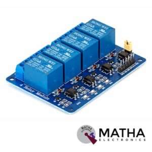

4 CHANNEL 12V RELAY
- 4-Channel relay interface board
- Relay input voltage: 12V DC
- Relay output: 5A/250V AC
- Signal input:5V DC from the microcontroller
- High current relay of 10A @250 V AC/10A@ 30V DC
- For quick and easy connection high-quality screw terminals provided
- Can control both AC & DC appliances such as DC motors, solenoid valves, lamps, etc.
- LED status indicates relay ON/OFF state.
- Power battery terminal for relay output and aux power connection
- Standard interface that can be controlled by a microcontroller (Arduino, 8051, PIC, AVR, DSP, ARM)
- Relay can directly control all equipment’s and loads
- For easy accessibility input signal pin connected to burg sticks
- Dimension: 165*65*1mm
- Weight: 7gm


DS3231 RTC MODULE
- Operating voltage of DS3231: 2.3 v to 5.5v
- 400Khz I2C interface
- Automatic power failure battery switch circuitry
- RTC counts seconds, minutes, hours, and year
- High precision clock chip DS3231
- Programmable square-wave output
- Chip temperature sensor accuracy:+/_3 degree Celsius
- Memory chip: AT24C32 with 32K storage capacity
- CR2032 battery backup with a high life span
- Low power consumption
- Register for ageing trim
- Dimension: 38mm*22mm*14mm

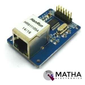
ENC28J60 ETHERNET MODULE
- ENC28J6 Ethernet chips, SOP28 package
- Operating voltage: 3.1V to 3.6V (3.3 V typical)
- Operating temperature: -40 degree to +85 degree Celsius
- IEEE 802.3 compatible Ethernet controller
- Buffer size: 8Kb
- Supports full and half-duplex mode
- SPI interface with a clock speeds up to 20MHz
- Programmable automatic rejection of erroneous packets
- Programmable automatic retransmit on a collision
- Programmable padding and CRC generation
- 25 MHz crystal oscillator
- Clock out the pin with a programmable presale
- Ethernet LAN module for Arduino/AVR/LPC/STM3
- 5V tolerant inputs
- SPI interface
- Led power indicator
- Dimension: 58*34*17mm


I2C MODULE WITH 16*2 CHARACTER LCD
- Supply voltage: 5V
- Display mode: STN
- Display format: 16*2
- Input data: 4 bit or 8 bit (for LCD)
- I2C address: 0x20~0x27 (original address is 0x20,we can change it ourselves)
- Compatible with multiple communication logic levels: 2.8~5VDC
- Compatible for 16*2 LCD
- Serial I2C control of LCD display using PCF8574
- Allow data display via only 2 wires.
- Backlight and contrast adjustment by the potentiometer
- Supports 7 ASCII fonts, 5 graphic functions
- Supports 128 level backlight lightness adjustment.
- Support 64 level screen contrast adjustment
- Supports device address modification
- Dimension: 10*4*5cm
- Size: 150gm


IRF520 MOSFET DRIVER MODULE SENSOR
- Operating Voltage: 3.3v & 5v
- Digital level port
- Output load voltage: 0-24v
- Output load current: <5A
- The heat sink is added for currently more than 1A
- Compatible with Arduino, MCU, ARM, Raspberry pi
- PWM dimming LED used to step-less dimming, variable-speed motor
- Output PWM can be adjusted by the original IFR520 MOS
- Arduino can drive up to 24V, such as led lights, dc motors, miniature pumps, solenoid valves etc.
- Dimension:34*30*18mm
- Size: 10gm
Reviews
There are no reviews yet.