
I am text block. Click edit button to change this text. Lorem ipsum dolor sit amet, consectetur adipiscing elit. Ut elit tellus, luctus nec ullamcorper mattis, pulvinar dapibus leo.
-15%Sold out

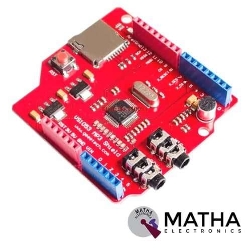
VS1053 MP3 Recording Module Development Board with Onboard Recording For UNO
Original price was: ₹1,855.00.₹1,400.00Current price is: ₹1,400.00. inc. GST
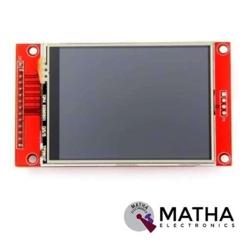
2.8 inch SPI Screen Module TFT Interface 240 x 320 without Touch
Original price was: ₹1,725.00.₹1,500.00Current price is: ₹1,500.00. inc. GST
“PWM Generator Module for Stepper Motor Driver with Forward and Reverse Function “
Original price was: ₹1,825.00.₹1,550.00Current price is: ₹1,550.00. inc. GST
- Board can be used to generate PWM signals for the stepper motor driver
- Operating Voltage: 12VDC
- Three Frequency Range
- Forward and Reverse Function.
- It has three frequency ranges selectable via onboard jumpers.
- Frequency can be measured via PUL and common cathode (GND) ports.
- The board has two sets of power input
Out of stock
Description
The TOSHIBA 2SC5200 was used to create this PWM Stepper Motor Controller Board. This board is used to create PWM signals for the stepper motor driver, and it features onboard buttons for rotating the stepper motor in both CW and CCW directions. The motor’s speed may be adjusted using the onboard potentiometer. The onboard jumper can be used to choose the high and low frequency signals when the board creates a frequency pulse signal.
In the speed control of DC motors, pulse-width modulation (PWM) or duty-cycle variation techniques are often utilised. During a PWM period, the duty cycle is defined as the fraction of digital ‘high’ to digital ‘low,’ as well as the digital ‘high’ pulse-width. This great method of controlling the amount of power delivered to a load without dissipating any wasted power.
Note:
- In order to use the start or stop function, the ENA enable terminal on the controller must be connected to the driver with a common cathode or a common anode.
- The forward and reverse rotation and the start and stop of the motor can be controlled by pressing the button.
- Changing the frequency of the motor may be regulated by altering the potentiometer.
- An ordinary switch with self-locking is used to control the motor’s forward/reverse rotation and start/stop function.
- Incase, If you want to connect the switches that control forward and reverse, and open or stop, to the chassis panel, you can refer to the following instructions.
- Change the forward and backward buttons, as well as the start-stop button, into a lead-wire switch, as shown on the rear.
Reviews (0)
Shipping & Delivery

Related products

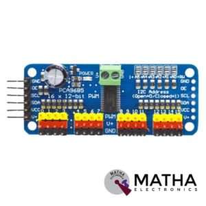
16-Channel 12-bit PWM/Servo Driver I2C interface PCA9685 for Arduino Raspberry Pi
- Adjustable frequency PWM up to about 1.6 kHz
- 12-bit resolution for each output – for servos, that means about 4us resolution at a 60Hz update rate
- Configurable push-pull or an open-drain output
- The output enable pin to quickly disable all the outputs
- Terminal block for power input
- Reverse polarity protection on the terminal block input
- Green power-good LED
- 3 pin connectors in groups of 4 so you can plug in 16 servos at once
- Chainable design
- A spot to place a big capacitor on the V+ line
- 220-ohm series resistors on all the output lines to protect them, and to make driving LEDs trivial.
- This board/chip uses an I2C 7-bit address between 0x60-0x80, selectable with jumpers.

5-36v Switch Drive High-power MOSFET Trigger Module
- Operating Voltage: DC 5V - 36V;
- The trigger source: digital high-low (DC3.3V - 20V), can be connected microcontroller IO port, PLC interfaces, DC power, you can access the PWM signal, the signal frequency 0--20KHZ perfect support.
- Output capacity: DC 5V - 36V, at room temperature, continuous current 15A, power 400W! Lower auxiliary cooling conditions, the maximum current up to 30A.
- Applications: You can control the output of power equipment, motors, light bulbs, LED lights, DC motors, micro-pumps, solenoid valves, etc.. You can enter
- PWM, motor speed control, lamp brightness.
- Availability: unlimited switch
- Operating temperature: -40-85
- Dimension: 34mm x 17mm x 12mm
- The use of imported dual-MOS parallel active output, lower resistance, more current, strong power at room temperature, 15A, 400W, to meet the most use of the equipment
- Wide voltage, the perfect support for PWM
- Easily control high power devices
- Input PWM to achieve motor speed control, lamp brightness control
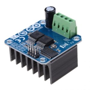
BTS7960 43A High Power Motor Driver Module/Smart Car Driver Module for Arduino Current Limit
- Input voltage: 6V-27V
- Maximum current: 43A
- Input level: 3.3-5V
- Control mode: PWM or level
- Duty cycle: 0-100%
- Double BTS7960 large current (43 A) H bridge driver
- 5V isolate with MCU and effectively protect MCU
- 5V power indicator on board
- Four lines from MCU to driver module (GND. 5V. PWM1. PWM2)
- Reverse the motor forward, two PWM input frequency up to 25kHZ
- Two heat flow passing through an error signal output
- Dimension: Approx. 4 * 5 * 1.2cm

DRV8825 Stepper Motor
- Operating voltage: 8.2V to 45V
- Continuous current per phase: 1.5 Amp
- Maximum current per phase: 2.2 Amp
- Minimum logic voltage: 2.5V
- Maximum logic voltage: 5.25V
- Six different step resolutions: full-step, half-step, 1/4-step, 1/8-step, 1/16-step, and 1/32-step
- Compatible with 3V3 and 5V microcontrollers
- Our Board comes with 0.1 Ohm Sensor resistors
- The Correct current decay mode (fast decay or slow decay) selected by chopping control
- Over-temperature thermal shutdown, under-voltage lockout, and crossover-current protection
- Short-to-ground and shorted-load protection
- 4-layer, 2 oz copper PCB for improved heat dissipation
- Exposed solderable ground pad below the driver IC on the bottom of the PCB
- Dimensions : 15 x 20 mm.
- Weight: 4 gm.

Leadshine DM320C
- Supply voltage up to +30 VDC
- Output current programmable, from 0.3A to 2.0A
- Pulse input frequency up to 70 kHz
- TTL compatible and optically isolated input
- Automatic idle-current reduction
- Suitable for 2-phase and 4-phase motors
- Support PUL/DIR and CW/CCW modes
- Over-voltage, over-current, phase-error protection
- Anti-Resonance provides optimum torque and nulls mid-range instability
- Self-test and Auto-configuration technology offers optimum responses with different motors
- Microstep resolutions programmable, from full-step to 102,400 steps/rev
- Support PUL/DIR and CW/CCW modes
- Over-voltage, over-current, phase-error protection
- Its unique features make the DM320C an ideal solution for applications that require low-speed smoothness
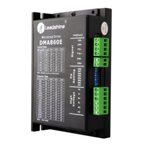
Leadshine DMA860E Stepper Motor Driver
- Model: DMA860E.
- Control Mode: Step & Direction.
- Max Input Frequency: 200 kHz.
- Input Voltage Range: 18 - 80 VAC / 24 - 110 VDC.
- Suggested Power Supply Voltage Range: 36-90 VDC /24-60 VAC.
- Number of DIP Switch Resolution Configurations: 16.
- 16 selectable micro-step resolutions of 400-51,200 via DIP switches.
- 8 selectable output current settings of 2.4 – 7.2A via DIP switches.
- Logic Current Range: 7-16mA (10mA typical).
- Logic Voltage Range: 4-5 VDC for pulse active high (default), or 0-0.5V for pulse active low.
- Pulse enabled at: Rising edge.
- Idle Current Percentage: 50 %.
- Number of Digital Inputs: 3.
- Step Width: 2,500 ns.
- Minimal Direction Setup Time: 5,000 ns.
- Isolation Resistance: 500M Ohm..
- Ambient Temperature: 0-50°C.
- Humidity: 40–95% RH.
- Operating Temperature: 0-70°C.
- Vibration: 5.9 m/s2 Max.
- Motor auto-identification and parameter auto-configuration for optimal torque from wide-range motors.
- Step & direction (PUL/DIR) and CW/CCW (via internal jumper set) control. Step & direction by default Multi-Stepping for smooth motor movement.
- Opto Isolation for input control signals.
- Soft-start with no “jump” when powered on.
- Protections for over-voltage and over-current.
- Dimension: 5.94 X 3.82 X 2.24 Inches.
- Weight: 1.13 lbs.
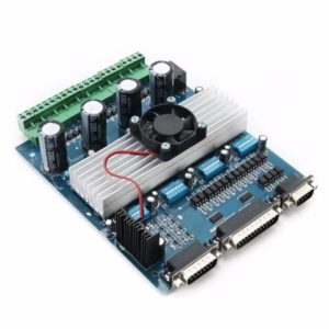
TB6560 4 Axis Cnc Controller 4 Axis Stepper Motor Driver DSP Controlled 3.5A 24V
- Rated maximum output: ± 4.5A, 40V, Peak 5A, low output impedance, source 0.5?,
- the receiving end of 0.4?, low voltage shutdown, thermal parking and circulation.
- circuit protection. After I design, you can set the current output of 0.5A 1A 1.8A 2.5A.
- 3.3A 4A 4.5A to accommodate more and different motor Current.
- The drive is suitable software mach2, mach3, (mach3 have support WIN7 system), KCAM4 like.
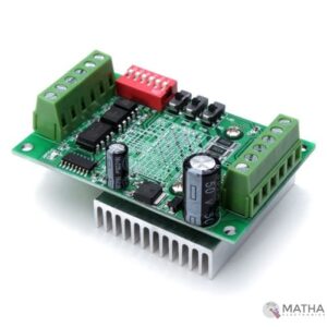
TB6560 Driver Board 3A CNC Router Single 1 Axis Controller Stepper Motor
- Supply voltage up to +32 VDC
- Output current up to 3.0A
- Pulse frequency up to 20 KHz
- Suitable for 2-phase and 4-phase motors
- Over-voltage and short-circuit protection
- 7 output current choices, max 3200 steps/rev
- Automatic idle-current reduction
- Single-chip motor driver for sinusoidal micro-step control of stepping motors
- High output withstands voltage due to the use of BiCD process:
- Forward and reverse rotation
- Selectable phase excitation modes (2, 1-2, 2W1-2, and 4W1-2)
- High output withstand voltage: VDSS = 40 V
- High output current: IOUT = TB6560AHQ: 3.5 A (peak)
- Internal pull-down resistors on inputs: 100 kΩ
- Output monitor pin: MO current (IMO (max) = 1 mA)
- Reset and enable pins
Reviews
There are no reviews yet.