
I am text block. Click edit button to change this text. Lorem ipsum dolor sit amet, consectetur adipiscing elit. Ut elit tellus, luctus nec ullamcorper mattis, pulvinar dapibus leo.
-13%

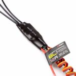
EMAX BLHELI 12Amp ESC for Quadcopter / Drones
Original price was: ₹800.00.₹750.00Current price is: ₹750.00. inc. GST

Leadshine DMA860E Stepper Motor Driver
Original price was: ₹6,000.00.₹5,700.00Current price is: ₹5,700.00. inc. GST
Wemos D1 Mini ESP8266 NodeMCU WIFI board for Arduino
Original price was: ₹400.00.₹350.00Current price is: ₹350.00. inc. GST
- Microcontroller: ESP-8266EX
- Operating Voltage: 3.3 V
- Digital I/O Pins: 11
- Analog Input Pins 1(Max input: 3.2V)
- Clock Speed: 80MHz/160MHz
- Flash: 4M bytes
- Length: 34.2mm
- Width: 25.6mm
- Use BRT (Bias Resistor Transistor)
- Easier into flash mode.
- 30% increase in radiating area
- Good stability.
- 11 digital input/output pins, all pins have interrupt/PWM/I2C/one-wire supported(except for D0)
- 1 analog input(3.2V max input)
- Micro USB connection
- Compatible with Arduino
- Compatible with Node MCU
- Support OTA wireless uploading
- 11 x I/O pins,1 x ADC pin
Description
The Esp8266 D1 Mini NodeMCU Wi-Fi Development Board based on ESP8266 designed as an Arduino Compatible Mini wifi board. This Wi-Fi board with 4MB flash specifically to fulfill the needs of a new connected world. It gives access to any microcontroller to your Wi-Fi network. This D1 mini board consists of 11 digital input/output pins, with all pins have interrupt/PWM/I2C/one-wire supported (except D0) 1 analog input(3.3V max input), and a Micro USB connection. D1 Mini NodeMCU provides on board switching power supply in which the board is powered using a 12v power supply.
In short D1 mini is an ESP8266 development board that is compact, versatile, and very easy to use with the Arduino IDE and Node MCU. The development board features with self-contained SOC and an integrated TCP/IP protocol stack. Thus It gives access to any microcontroller to your WiFi network. Moreover, this NodeMCU designed with ESP8266 based serial Wi-Fi integrated onboard capable of providing GPIO, PWM, ADC, I2C, and 1-WIRE resources. This module flashed with the latest firmware version and using the onboard micro USB connection can be set up and programmed right away. While providing a wireless internet connection for embedded devices it comparatively consumes low power. Moreover, due to its small form factor its easily integrated into resource-limited devices.
APPLICATIONS:
- Wireless communication between two microcontrollers
- Communicate with Laptop, Desktops and mobile phones
- Data Logging application
- Consumer applications
- Wireless Robots
- Home Automation
Reviews (0)
Shipping & Delivery

Related products
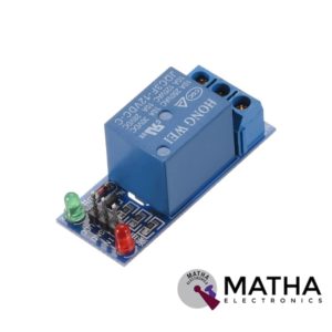
1 CHANNEL 12V RELAY
- 1-Channel relay interface board
- Operating voltage: 12V DC
- Provide high current relay of 15A
- For quick and easy connection high-quality screw terminals provided
- Can control both AC & DC appliances
- LED status indicates relay ON/OFF state.
- High current relay of 10A @250 V AC/10A@ 30V DC
- Standard interface that can be controlled by a microcontroller (Arduino, 8051, PIC, AVR, DSP, ARM)
- For easy accessibility input signal pin connected to burg sticks
- Dimension: 43*17*17mm
- Weight: 150gm


2 CHANNEL 5V RELAY
- High current relay
- Two LED S to indicate relays ON/OFF status
- Low-level trigger expansion board
- Opto isolation circuitry
- Works with logic level signal 3.3V or 5V devices
- Can be used as normally open (NO) or normally closed (NC)
- Back EMF protection
- Ensures diode current protection
- AC control voltage: 250v @mx10A
- DC control voltage: 30V @max 10A
- Easy installation and fixing
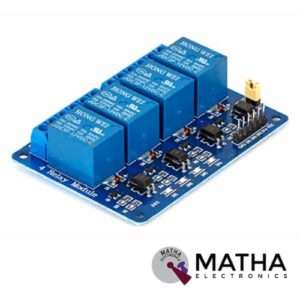

4 CHANNEL 12V RELAY
- 4-Channel relay interface board
- Relay input voltage: 12V DC
- Relay output: 5A/250V AC
- Signal input:5V DC from the microcontroller
- High current relay of 10A @250 V AC/10A@ 30V DC
- For quick and easy connection high-quality screw terminals provided
- Can control both AC & DC appliances such as DC motors, solenoid valves, lamps, etc.
- LED status indicates relay ON/OFF state.
- Power battery terminal for relay output and aux power connection
- Standard interface that can be controlled by a microcontroller (Arduino, 8051, PIC, AVR, DSP, ARM)
- Relay can directly control all equipment’s and loads
- For easy accessibility input signal pin connected to burg sticks
- Dimension: 165*65*1mm
- Weight: 7gm

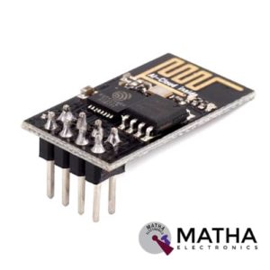
ESP8266 ESP – 01
- 11 b/g/n
- Wi-Fi Direct (P2P), soft-AP
- Integrated TCP/IP protocol stack
- Integrated TR switch, balun, LNA, power amplifier and matching network
- Integrated PLLs, regulators, DCXO and power management units
- +19.5dBm output power in 802.11b mode
- Power down leakage current of <10uA
- 1MB Flash Memory
- Dimensions: 25 x 15 x 11 mm (LxWxH)
- PCB Thickness: 1mm
- Weight: 2 gm
- SDIO 1.1 / 2.0, SPI, UART
- STBC, 1×1 MIMO, 2×1 MIMO
- A-MPDU & A-MSDU aggregation & 0.4ms guard interval
- Wake up and transmit packets in < 2ms
- Standby power consumption of < 1.0mW (DTIM3)
- Integrated low power 32-bit CPU could be used as an application processor
- A-MPDU & A-MSDU aggregation & 0.4ms guard interval
- Wake up and transmit packets in < 2ms
- Standby power consumption of < 1.0mW (DTIM3)


ESP8266 ESP-12E
- LDR Light Sensor on board.
- WS2812 Led on board.
- Wireless Standard: IEEE 802.11 b/g/n protocol
- Frequency Range: 2.412 - 2.484 GHz
- Serial Transmission: 110 - 921600 bps, TCP Client 5
- SDIO 2.0, SPI and UART Interface available
- PWM available
- One ADC channel is available
- Programmable GPIO available
- Wireless Network Type: STA / AP / STA + AP
- Security Type: WEP / WPA-PSK / WPA2-PSK
- Encryption Type: WEP64 / WEP128 / TKIP / AES
- Network Protocol: IPv4, TCP / UDP / FTP / HTTP
- Operating Voltage: 3.3V
- Maximum current allowed to draw per pin: 15mA
- Power down leakage current of < 10uA
- Integrated low power 32-bit MCU
- Onboard PCB Antenna
- Wake up and transmit packets in < 2ms
- Standby power consumption of < 1.0mW
- Operating Temperature: -40ºC to +125 ºC

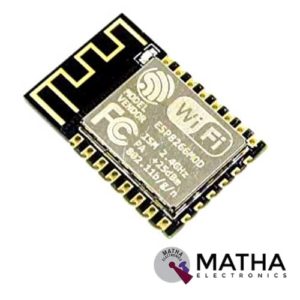
ESP8266 ESP-12F
- Communication interface voltage: 3.3V
- Working current: 240mA(MAX)
- Serial port baud rate: 115200 (default), can be modified to other values by AT command
- Serial communication format: 8N1
- Wireless Network Mode: station / softAP / SoftAP + station
- Wireless criteria: 802.11 b / g / n
- WIFI @ 2.4 GHz, support for WPA / WPA2 security mode
- +19.5dBm output power
- Compatible with ESP-12(ESP-202)
- It is very easy to develop projects with AT commands
- Surface Mount Package with 2mm Pitch Pads
- Mulitple GPIO’s for all your sensor needs
- Integrated TCP/IP protocol stac
- Integrated TR switch, balun, LNA, power amplifier and matching network
- Integrated PLL, regulators, DCXO and power management unit
- Power down leakage current of <10uA
- Integrated low power 32-bit CPU could be used as an application processor
- SDIO 1.1/2.0, SPI, UART
- STBC, 1×1 MIMO, 2×1 MIMO
- A-MPDU & A-MSDU aggregation & 0.4ms guard interval
- Wake up and transmit packets in < 2ms
- Standby power consumption of < 1.0mW (DTIM3)
- Both SMD and Inline package are available, and the pin pitch is 2.0mm.

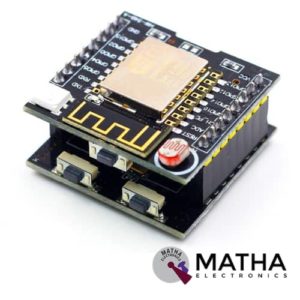
ESP8266 Serial WIFI Witty Cloud Development Board ESP-12F Module MINI Nodemcu
- LDR Light Sensor on board
- WS2812 Led on board
- 3x tactile buttons (1x in the Witty board and 2x in theCH340 board)
- Micro USB connection for power and/or programming
- Uses latest ESP-12F module with 4M flash and integrated antenna
- Includes CH340G USB-to-UART programmer
- Includes LDR (light dependent resistor a.k.a photoresistor) connected to ESP’s ADC pin
- RGB LED connected to GPIO 12,13 and 15
- It supports 3 modes AP, STA, AP+STA
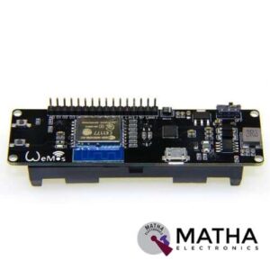
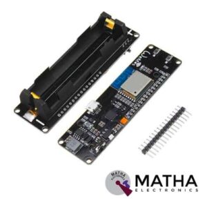
WeMos D1 ESP Wroom 02 Board ESP8266 Mini WiFi Nodemcu Module 18650 Battery
- One AD inputs.
- Micro USB inputs.
- One programmable LED (D0).
- AUTO PROGRAM circuit.
- ESP8266 (ESP-WROOM-02 With TELEC) is equivalent to the NodeMCU.
- Analog Input (AD): Built-in dividing resistor (AD = 220K ADC 100K = GND).
- There is a SOLDER terminal for SLEEP MODE.
- Compatible With Arduino andNodeMCU.
- Operation and charging are possible at the same time.
- 18650 charging circuit including the 5V boosting circuit with TP5410.
- Overcharge protection, over-discharge protection built-in.
- LED: Red = Charging, Green = Full charging.
- 3000 mA 18650 It is possible to operate for more than 17 hours on a battery.
- Integrated 18650 battery charging and discharging system.
- One switch controls whether the 18650 battery is on power or not.
- OLEDs SDA and SCL can connect to the D1 pin and the D2 pin respectively.
- The five buttons can be controlled by FLATH, RSET, D5, D6, and D7 respectively.
- The 5 Digital pins can configure the write/read/interrupt/PWM/I2C/one-wire supported separately.
- Operation and NodeMCU consistent, adding a programmable LED, you can use GPIO16 to control; display 8266 running status and other functions. Integrated OLED and five buttons, more convenient for development.
- The design concept originates from the open-source project NodeMCU; the development board integrates 18650 charging and discharging systems with charging and discharging protection. At the same time, an OLED and five directional buttons are integrated to facilitate the development.
Reviews
There are no reviews yet.