
SIMPLE 2-AXIS SERVO ROBOTIC ARM CONTROLLED BY MPU-6050
Robotic Arms are one of the fascinating engineering creations and it is always fascinating to watch these things tilt and pan to get complex things done just like a human arm would. These robotic arms can be commonly found in industries at the assembly line performing intense mechanical work like welding, drilling, painting, etc., recently advanced robotic arms with high precision are also being developed to perform complex surgical operations.
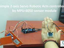
Here we design a simple 2-axis servo robotic arm using an MPU-6050 accelerometer-gyro sensor. This is a highly efficient and cost-effective system. This 3D printed robotic arm position is controlled through a hand glove that is attached with an MPU6050 Gyroscope and a flex sensor. The Flex sensor is used to control the gripper servo of the Robotic Arm and the MPU6050 is used for the movement of the robotic in the X and Y-axis.
PROPOSED SYSTEM:
A Robot is an electro-mechanical system that is operated by a computer program. Robots can be autonomous or semi-autonomous. An autonomous robot is not controlled by human and acts on its own decision by sensing its environment.Majority of the industrial robots are autonomous as they are required to operate at high speed and with great accuracy. But some applications require semi-autonomous or human controlled robots.One of the frequently implemented motion-controlled robots is a Hand Gesture Controlled Robot. In this project, a hand gesture controlled robot is developed using MPU6050, which is a 3-axis Accelerometer and 3-axis Gyroscope sensor and the controller part is Arduino Uno.
In this project, we are about to design a simple 2-axis servo robotic arm using an MPU-6050 accelerometer-gyro sensor. The MPU-6050 is a sensor based on Micro Electrical Mechanical System (MEMS) technology. In this sensor module, the accelerometer and the gyroscope are embedded in a single chip using the I2C protocol to communicate. It has a 3 axis accelerometer and 3- axis gyroscope inbuilt in it. This helps to measure the acceleration, voltage, orientation, displacement, and many parameters of a system. An onboard Digital Motion Processor in this module is used to process the 6 axis fusion algorithm. Thus provide a complete 9 axis motion fusion output by accessing the external magnetometer.MU-6050 is a low-cost and highly accurate sensor with an I2C bus. Each finger is controlled with help of individual servo motor. Servo motor gets its signal from Arduino which determines the position of the motor. A flex sensor is used as input to the Arduino which gives the position of the bent finger the user does. The flex sensor is mounted on the gloves which the user can wear.
HARDWARE REQUIREMENTS:
- Arudino Uno
- MPU-6050 Gyro Sensor
- Flex sensor (2.2″) x5
- Servo motor x5
- 9v 1A adapter
- 3D Printed Robotic hand
ARDUINO UNO
Although there are many types of boards from Arduino. Here we are about to use Arduino Uno as it is very common. The Arduino Uno has:
· Operating voltage is 5V
· The recommended input
· Voltage will range from 7v to 12V
· Digital input/output pins are 14
· Analog i/p pins are 6
· DC Current for each input/output pin is 40 mA
· Flash Memory is 32 KB
· SRAM is 2 KB
· EEPROM is 1 KB
· CLK Speed is 16MHz
Another wonderful feature of the Arduino is the option of using an add-on board to the Arduino which comes as a module and they are known as “Shields”

MPU6050 Gyro Sensor
The MPU-6050 is a sensor based on Micro Electrical Mechanical System (MEMS) technology. In this sensor module, the accelerometer and the gyroscope are embedded in a single chip using the I2C protocol to communicate, which helps to measure the acceleration, voltage, orientation, displacement, and many parameters of a system. An on-board Digital Motion Processor in this module is used to process the 6 axis fusion algorithm to provide a complete 9 axis motion fusion output by accessing the external magnetometer.MU-6050 is a low-cost and highly accurate sensor with an I2C bus.
An easy and interesting project in which you use an MPU6050 (Accelerometer + Gyro) sensor module to control a simple 2-axis Servo Robotic Arm

Examples where MPU-6050 may be used
· Automotive industry – To deploy airbags, Vehicle roll handling
· Game controllers – Wii remote/ Wii mote
· Gimbal/ Camera stabilization system
· Hard drives
· Personal Digital Assistants – Smartphones, tablets
· Robotics
· Unmanned Aerial Vehicles (UAV) – Drone, helicopters
· Vehicle Navigation
APPLICATIONS OF MPU-6050
· Automotive industry – To deploy airbags, Vehicle roll handling
· Game controllers – Wii remote/ Wii mote
· Gimbal/ Camera stabilization system
· Hard drives
· Personal Digital Assistants – Smartphones, tablets
· Robotics
· Unmanned Aerial Vehicles (UAV) – Drone, helicopters
· Vehicle Navigation.
Micro Servo Motor
Micro servo motors is rotatory or linear actuator. It provides precise control of linear and angular position, velocity, and acceleration. They are useful in many robotics projects, such as for turning the front wheels on an RC model for steering or pivoting a sensor to look around on a robotic vehicle.
Servo is a general term for a closed-loop control system that consists of a suitable motor, couple to a sensor for position feedback signal, in order to adjust the speed and direction of the motor and to achieve the desired result.
A servo motor works with a small DC motor connected to the output shaft through the gears. The output shaft drives a servo arm which is connected to the potentiometer (pot). The potentiometer provides position feedback to the servo control unit where the current position of the motor is compared to the target position.
How Servo Motors Work
A servo motor can be controlled by sending a series of signal pulses to the signal. A conventional analog servo motor can receive a pulse roughly every 20 milliseconds (i.e. signal should be 50Hz). The position of the servo motor determines the length of the pulse.
• If the pulse is high for 1ms, then the servo angle will be zero.
• If the pulse is high for 1.5ms, then the servo will be in its center position.
• If the pulse is high for 2ms, then the servo will be at 180 degrees.
In this servo motor, the pulses ranging between 1ms and 2ms will rotate the servo shaft to full 180 degrees of its travel.
.96 INCH OLED DISPLAY (SSD1306)
4 PIN White OLED module is a 0.96 inch 4 pin module with SSD1306 DRIVER IC that can be interfaced with any microcontrollers using SPI/IIC protocol. These modules have high brightness, high contrast ratio, low power consumption, and wide viewing angle. This is compact in size and provides a high resolution of 128*64. Here OLED doesn’t require any backlight as a result it possesses high application for all types of display. This module ensures low power consumption in which 0.06 W is required for normal operation·
