
Three-level Ultra security system using Arduino
In the world we live in today, robberies have significantly risen. Consequently, everything needs to be protected by utilizing a security system. This handy little security system project, named ULTRA SECURITY SYSTEM, is modest but incredibly effective.
This system is three-way protected and has three sensors that will notify the user if there is a breach attempt. I’ve broken down the three components of this Ultra security system into separate explanations to make things simpler. Let’s examine the three levels of security.
1) LDR AND LASER LEVEL IN ULTRA SECURITY SYSTEM:
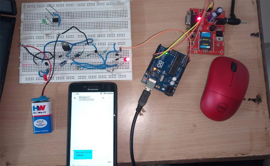
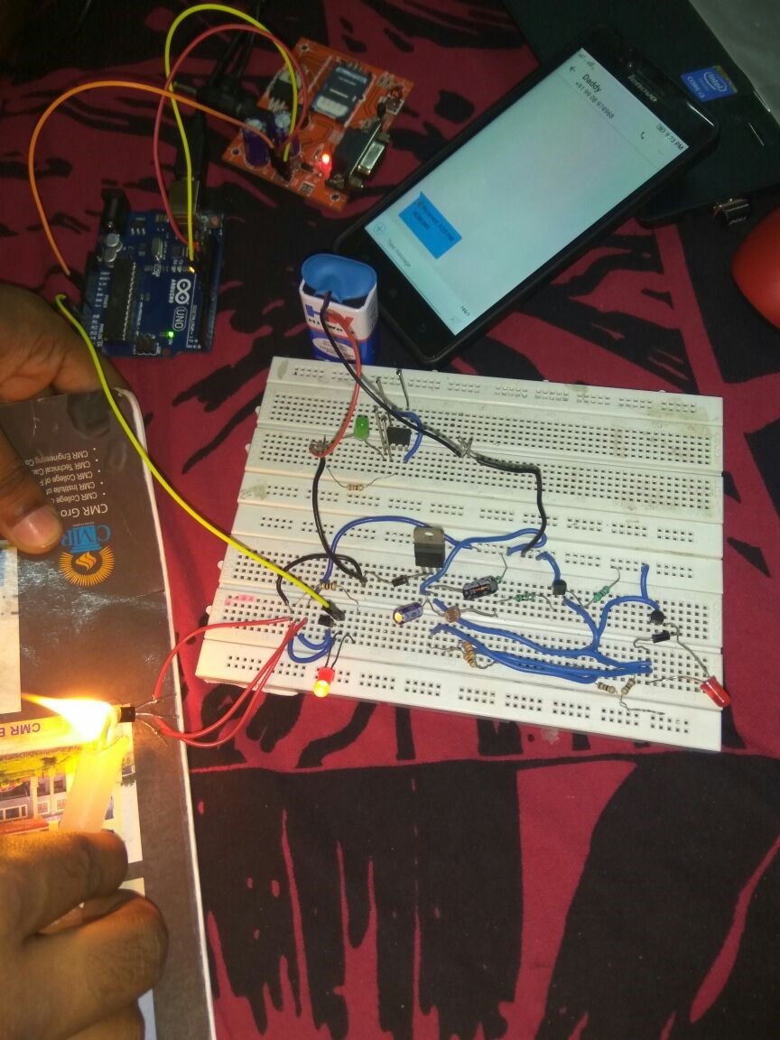
This is the initial stage in detecting a bank heist. When the robber tries to access the BANK cell, the LDR sensor in the locker light deviates and the Arduino directs the GSM module, which then sends a text message with the subject “ROBBERY” to the registered mobile number or the closest police station.
Components Used:
- LDR
- ARDUINO
- GSM Module
- NPN Transistors BC 547
- Diodes (1N 4007)
- Red LED
- Capacitors (1 uF)
- Voltage Regulator(7805)
- Resistors
- Batteries (9V)
Schematic Circuit:

Code:
| #include <SoftwareSerial.h> SoftwareSerial mySerial(9,10); //(tx,rx) aurdino float a=A2; int b,c; void setup() { mySerial.begin(9600); // Setting the baud rate of GSM Module Serial.begin(9600); // Setting the baud rate of Serial Monitor delay(100); } void loop() { b=analogRead(a); c=map(b,0,1023,0,10); Serial.print(c); Serial.print(“/”); delay(1000); if(c<3) { mySerial.println(“AT+CMGF=1”); //Sets the GSM Module in Text Mode delay(1000); // Delay of 1000 milli seconds or 1 second mySerial.println(“AT+CMGS=\”+918500911427\”\r”); delay(1000); Serial.print(“ROBERRY”); mySerial.println(“ROBERRY”); delay(100); mySerial.println((char)26);// ASCII code of CTRL+Z delay(1000); } } |
2) LM35 LEVEL:
If the burglar uses a flame thrower or other heating tool to try to open the door using this technique. This LM35 heat sensor senses heat and uses Arduino to convey a message. The gsm module receives the order and then sends a text message with the subject “ROBBERY” to the registered mobile number or, if possible, to the closest police station.
Components Used:
- Arduino Uno
- GSM Module
- LM35 Sensor
Schematic Circuit:

Code:
| #include <SoftwareSerial.h> SoftwareSerial mySerial(9,10); //(tx,rx) aurdino float a=A2; int b,c; void setup() { mySerial.begin(9600); // Setting the baud rate of GSM Module Serial.begin(9600); // Setting the baud rate of Serial Monitor delay(100); } void loop() { b=analogRead(a); c=map(b,0,1023,0,10); Serial.print(c); Serial.print(“/”); delay(1000); if(c<8) { mySerial.println(“AT+CMGF=1”); //Sets the GSM Module in Text Mode delay(1000); // Delay of 1000 milli seconds or 1 second mySerial.println(“AT+CMGS=\”+918500911427\”\r”); delay(1000); Serial.print(“ROBERRY”); mySerial.println(“ROBERRY”); delay(100); mySerial.println((char)26);// ASCII code of CTRL+Z delay(1000); } } |
3) TOUCH SENSOR:

This kind of technique is also applied to robbery detection. When a thief tries to open a locker door by touching the handle, the sensor responds. The touchpad on the handle will alert Arduino, who then instructs the gsm module to do something. A text message with the subject “ROBBERY” is then sent by GSM to the registered mobile phone or the closest police station.
Components Used:
- Arduino
- GSM Module
- NE555
- Resistors
- Capacitors
- Touch Panel
Schematic Circuit:

Code:
| #include <SoftwareSerial.h> SoftwareSerial mySerial(9,10); //(tx,rx) aurdino float a=A2; int b,c; void setup() { mySerial.begin(9600); // Setting the baud rate of GSM Module Serial.begin(9600); // Setting the baud rate of Serial Monitor delay(100); } void loop() { b=analogRead(a); c=map(b,0,1023,0,10); Serial.print(c); Serial.print(“/”); delay(1000); if(c>30) { mySerial.println(“AT+CMGF=1”); //Sets the GSM Module in Text Mode delay(1000); // Delay of 1000 milli seconds or 1 second mySerial.println(“AT+CMGS=\”+918500911427\”\r”); delay(1000); Serial.print(“ROBERRY”); mySerial.println(“ROBERRY”); delay(100); mySerial.println((char)26);// ASCII code of CTRL+Z delay(1000); } } |
The three-layer hyper security system will be created by combining these three layers. Combining these three characteristics shouldn’t be difficult; all we have to do is give each sensor a separate analog pin and tell Arduino to keep checking them. Hope you enjoyed my project; give it a shot.
Conclusion
I hope all of you understand how to design a Three-level Ultra security system using Arduino. We MATHA ELECTRONICS will be back soon with more informative blogs.