
An Overview of Dual Power Supply-Circuit Construction and Working
Every electronic circuit requires the best for optimal performance. Most electronic components require a regulated DC power supply, and some applications require a dual power supply source comprising Positive (+V), Ground (GND), and Negative (GND) (-V). Using a step down transformer and linear voltage regulators, you may build a dual power supply circuit in this tutorial.

What is a Dual Power Supply?
A Dual power supply designed as a regular direct current power supply. It offers positive as well as negative voltage. It provides a consistent power supply to the device and aids in the prevention of system damage.
Dual power supplies are circuits that generate two different output voltages from a single input source. There are numerous types and configurations possible. The most common configuration provides two different positive DC voltage outputs or two equal magnitude and opposite polarity DC voltage outputs.
Why We Need Dual Power Supply?
1. The need for a Dual power supply in OPAMPS
In most cases, OPAMPS must swing bipolar output voltages. In response to the typical input signal range, one of them gets positive or negative. As a result, OPAMPS has two rails. As a result, we’ll require a dual power source to power the OPAMPS.
2. The need for a Dual power supply in Generators
We require a dual power supply when we want to run two different power circuits on the same power supply without taking it offline. It enables us to perform routine maintenance and other tasks on electrical equipment without having to turn it off.
3. The need for a Dual power supply in DIY
A dual power supply can be used as a cell phone charging circuit, a power bank circuit, in battery-less power circuits, and in the case of any direct current power source in DIY projects.
Types of Dual Power Supply
Most electronic circuit and application requires DC voltage range mostly falls in 5, 12 and 15 Volts, hence three types of dual power supply circuit listed as,
- 5 Volt Dual power supply circuit
- 12 Volt Dual power supply circuit
- 15 Volt Dual power supply circuit
All circuits have individual step down transformers and voltage regulators, you may include an LED indicator if you need.
5 Volt Dual power supply circuit diagram

12 Volt Dual power supply circuit diagram

15 Volt Dual power supply circuit diagram

Components Required
- Step down Transformer – center tap (6 or 15 or 20 VAc) depends on your need
- Bridge Rectifier Module or (1N4007 diode X 4)
- Capacitor 1000uF = 2, 10uF = 2, 0.1uF = 2. (Voltage range varies depends on circuit output voltage)
- Regulator IC (78XX = Positive), (79XX = Negative) choose voltage range depends on your need.
Construction And Working
- Construction
- Connect four diodes as shown in the figure to form a rectifier circuit.
- The rectifier’s input should be connected to the transformer’s secondary winding, while the output should be connected to the voltage regulator IC.
- A 1000F capacitor connects one of the voltage regulator’s input terminals to the ground.
- The output of these voltage regulators is our final output.
- Each reference terminal has a direct connection to the ground.
- Working:
Basically, any power supply consists of four blocks
- Transformer.
- Rectifier circuit.
- Filter circuit.
- Voltage Regulator.
Any power source has a 230V AC input, which we step down using a step-down transformer. This transformer converts 230 volts AC to 5 volts AC. Now we need DC voltage, which is provided by the rectifier circuit. The rectifier is responsible for converting the stepped-down AC voltage to DC voltage.
Once we got DC voltage does not mean the task is complete. To get stabilized DC voltage, we need a filter circuit. The capacitors in the circuit perform the filtering function. In the rectifier’s output, there are multiple peaks. Capacitors aid in the reduction of these peaks, completing the filtering process.
Now the main and the last task is voltage regulation. We’ll need to use a variety of voltage regulator ICs to fulfil this operation. For instance, 7812, 7912, and so on. In general, the 78xx series denotes a positive supply, while the 79xx series denotes a negative supply.
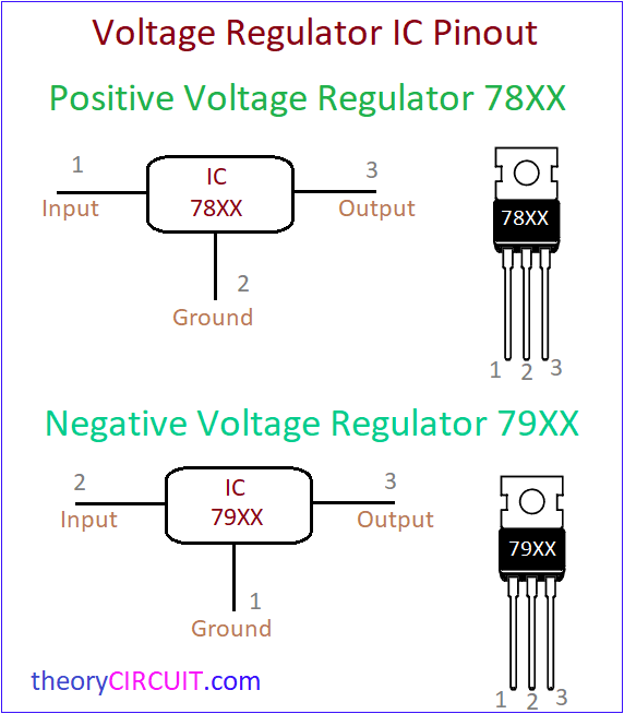
Voltage Regulator 78XX is responsible to regulate the positive side of DC voltage and 79XX is responsible to regulate the negative side of DC Voltage. These two voltage regulators’ pin configurations are shown, and the connections are made according to the pinout.
Capacitors C3, C4 eliminate any form of ripples in the DC supply on the output side, whereas Capacitor C5, C6 removes high frequency ripples on the positive and negative sides of the DC output. The common Ground supply is drawn straight from transformer (0)’s centre tap and serves as the Ground (GND) connector for the +V and -V DC supply outputs.
Voltage Regulator IC (78xx) (79xx)
- 78xx
The voltage regulator IC 78xx is also referred to as L78xx, LM78xx, or MC78xx. It’s the voltage regulator for positive voltage. Internal thermal overload and short circuit current limiting protection circuits are incorporated in. The maximum temperature at the junction is 125 degrees Celsius.
- 79xx
The voltage regulators in the 79xx series are negative voltage regulators. Negative voltage regulators are just as vital as positive voltage regulators. These ICs have three terminals and come in a set voltage range of -5v, -12v, and -15v. Internal thermal overload and short circuit current limiting protection circuits are also included.
Applications of Dual Power Supply Circuit:
- In Audio amplifiers, operational amplifiers, power amplifiers we use a dual power supply.
- In the low voltage direction of the DC motor, we can use this dual power supply.
- In 12V battery charging circuit.
- In a cell phone charging circuit.
- In a power bank circuit.
I hope all of you are clear about what is a Dual Power Supply Circuit is. We, MATHA ELECTRONICS, will be back soon with more interesting topics.
Fine notes for dual power supply