
Programming STM32F407VET6 using Arduino IDE
STM32F407 Discovery Board designed as a development board that is similar to Arduino in terms of advanced capabilities and accessibility. The STM32F407 Discovery Board enables the development of high-reliability applications by utilizing an advanced performance microcontroller known as the Arm Cortex-M4 32-bit core. I think you’re familiar with the ARM Architecture. It provides versatility and customization, allowing you to experiment with libraries, communication protocols, GPIO pins, and so on.
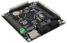
Here, We’ll go through the steps to programme the STM using the Arduino IDE without the use of an ST-Link or FTDI converter. I’m using the STM32F407VET6 Blackboard, which is capable of handling all single-precision data-processing instructions and data formats. Let’s get this party started!!
STM32F407VET6 Black Board:
It is a small STM32 Arduino compatible development board that features an STM32F407VET6 device as the microcontroller, and supports further expansion. It is ideal for starting application development with the STM32F family.
The STM32F407xx family is based on the high-performance Arm® Cortex®-M4 32-bit RISC core, which runs at up to 168 MHz. The Cortex-M4 core features a Floating point unit (FPU) single precision which supports all Arm single-precision data-processing instructions and data types. It also includes a memory protection unit (MPU) and a full set of DSP commands to improve application security.

High-speed embedded memories (Flash memory up to 1 Mbyte, up to 192 Kbytes of SRAM), up to 4 Kbytes of backup SRAM, and an extensive range of enhanced I/Os and peripherals connected to two APB buses, three AHB buses, and a 32-bit multi-AHB bus matrix are all included in the STM32F407xx families.
These devices offer three 12-bit ADCs, two DACs, a low-power RTC, twelve general-purpose 16-bit timers including two PWM timers for motor control, two general-purpose 32-bit timers. a true random number generator (RNG). They also feature standard and advanced communication interfaces.

STM32F407VET6 Features:
- Core: Cortex-M4 32-bit RISC.
- Onboard: SD card slot.
- RTC Battery: CR1220.
- Wireless Communication: NRF2401 Interface.
- Data storage: W25Q16.
- Support FMSC LCD Interface.
- Multi-user keys.
- All the CPU-10 lead.
- Arduino compatible.
- 2.54mm integer multiples spacing pin.
- Feature a full set of single-cycle DSP instructions.
- Operating Frequency: 168MHz, 210 DMIPS/1.25 DMIPS/MHz.
- Operating Voltage: 1.8V-3.6V.
- Package: LQFP100 Storage Resources: 512kB Flash, 192+4kB SRAM.
- Resource: 3 x SPI,3 x USART, 2 x UART, 2 x I2S, 3 x I2C; 1 x FSMC,1 x SDIO,2 x CAN; 1 x USB 2.0.
- FS/HS Controler(with DMA); 1 x USB HS ULPI; (used for external USB HS PHY)1 x 10/100 Ethernet.
- MAC;1 x 8 to 12-bit parallel camera interface; 3 x AD(12 bit,1us),2 x DA(12 bit).

For more knowledge regarding the STM32F407VET6 Blackboard, visit the Reference manual and programming manual.
DFU:
To interface with the device, we’ll utilise DFU as an uploading method. The DFU or DfuSe USB package is used to upgrade the firmware on STM32 microcontrollers over USB. Installation instructions can be found in AN3156 and UM0412.
The key benefits of the DFU Bootloader are:
- There’s no need for specialized equipment like JTAG, ST-LINK, or a USB-to-UART cable.
- Using USB, you may easily upgrade the firmware and programme the device.
Procedure:
- STM32CubeProgrammer software: Install STM32CubeProg software tool.
- Install Arduino IDE.
- Add this package in the preference of Arduino IDE.
- Go to Board Manager and Install STM32 Core Boards.
- Install DfuSe on your pc.
- Update driers for STM boot Loader through device manager.
- DFU mode is often selected by connecting Boot0 pin to 3.3v and Boot1 pin to GND.
- Select USB for communication using STMCubeMX software.

- In the Arduino IDE, choose the appropriate board, port, and upload method as DFU.

- Define the inbuilt LEDs. Onboard LEDs on STM32F407VET6 are PA6, PA7.
- Upload the Blink Code.
- Now you are all set to program STM through Arduino IDE.
I hope all of you are clear about how to programme the STM with the aid of Arduino IDE without using an ST-Link or FTDI converter.We, MATHA ELECTRONICS, will be back soon with more interesting topics.
On these boards in behind the JTAG connector are 4 pins (RX,TX,Vcc,Gnd) connected to UART1 ,I use a FTDI and cross connect the RX,TX lines ,then I set up the TOOLS in Arduino IDE for U(S)ART support ENABLED Gentic SERIAL ,USB support =NONE, the next 5 lines will set up automatically ,UPLOAD METHOD=STM32Cube Programmer DFU, now using a USB Data cable connect the FTDI to your computer and get the port info using Device Manager, Ensure it is correct in the Arduino IDE, Next open STM Cube Programmer,set it for UART,set thePort ,Baudrate and all the other port settings to match the info in the device manager, now Setup the BOOT 0,1 jumpers on the stm board (0 to 3.3vdc and 1 to gnd. Program the blinky in the Arduino IDE Now plug in both USB for FTDI and for the F407(only needs power) Hit UPload on the Arduino IDE and hit Reset after download sucess then remove and reset the boot jumpers to gnd ,now unplug the FTDI and the leds or led should be blinking . Hit reset again on the board again to be safe then you should be able to remove power from the F407 and plug it in again and it should run your blinky .