
Relays are electrically operated devices that may open or close contacts electronically. It can be used to turn on or off (make or break) circuits, control multiple circuits with a single signal or control high-power circuits using low-power signals. In this blog, we discuss what a relay is? Its construction, working, configurations, advantages and disadvantages, and applications.
What is a Relay?
A Relay is an electro-mechanical or solid-state device, used to control a device or a circuit electrically by applying a control signal to its coil. It is also known by the names auxiliary, miniature or control relay.
A relay is designed as an electrically operated switch. Many relays operate with an electromagnet to mechanically operate a switch. But other operating principles are also used, like solid-state relays. Relays functions where it’s necessary to regulate a circuit by a low-power signal. This peformed with complete electrical isolation between control and controlled circuits, or several circuits that should be controlled by one signal. Relays are mainly used for circuit components preferred in telecom applications, gas detector circuits, RF control applications, Infrared control applications, small volume circuits (gum relay), etc.
A protective relay is a device that detects the fault (any abnormal state in the power system is known as a fault) and initiates the operation of the circuit breaker to isolate the faulty element from the rest of the healthy power system.
Relay Terminology
The application of electrical relay can be understood using the below parts. It consists of
- Pole – Several isolated circuits that a relay can switch
- Throw – A number of closed contact positions per pole
- Contact form– The number of contacts and contact mechanism
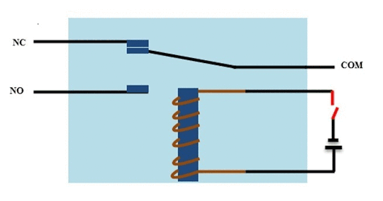
- Normally open– In this position, the contacts will connect the circuit (close) when the relay is actuated.
- Normally closed– Here, the contacts will disconnect (open) when the relay is actuated.
- Changeover contact– It can control two circuits. One terminal is normally open and normally closed in contact with a common terminal.
- Contact rating or Power rating-This specifies the amount of power the relay can switch a device that is connected as load. The relay ratings should be considered while using a relay for AC and DC switching. For example, a relay operated with 12V DC and a current rating of 10Amperes can switch less than or equal to 10A.
- Voltage– A source voltage to be applied to the coil
- Current– The amount of current flow in the relay when the nominal voltage is applied
Construction of a Relay
A typical electromechanical relay consists of the following components:
- Electromagnetic coil
- Armature
- Core
- Movable contacts
- Spring return arrangement
- Electromagnetic coil
An electromechanical relay’s most critical component is the electromagnetic coil. It is made up of a magnetic core and a collection of copper windings. The flow of current through the coil produces a magnetic field, as you may know. When voltage is given to the coil, it transforms into an electromagnet, attracting the armature.
- Armature
An armature is a movable piece of metal, balanced using a pivot.
- Core
The core is the metallic part over which the coil is wound.
- Movable contacts and fixed contact
The contacts inside the relay are the conducting elements that open or close when voltage is delivered to the coil. A movable contact is one that is attracted by an electromagnet, while a fixed contact is one that is immovable and attached to the terminals.
- Spring arrangement
They also have spring arrangements, such as those that return the armature and contacts to their original positions after the coil is de-energized.
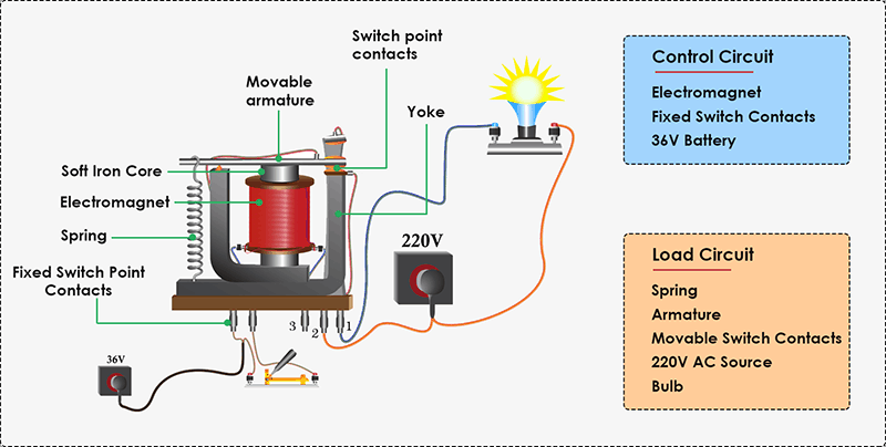
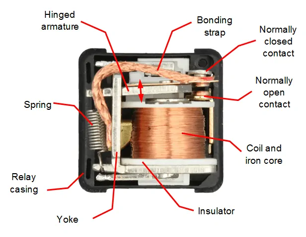
From the above diagram, the relay has two circuits namely the control circuit and the load circuit which are physically isolated. The load circuit has moveable switch contacts, movable armature, spring, and the load (Bulb) to be operated, while the control circuit has an electromagnet and Fixed Switch contacts.
The electromagnet is the most crucial component of the relay. It has a soft iron core that has been coiled by a coil. Initially, it lacks the magnetic property. When a voltage is supplied to the coil winding, however, it takes on the properties of a magnet. Because a metal wound with copper wire can act as a magnet when a voltage is applied to it.
The contacts can be made or broken by the moveable armature. Until the magnets is charged, the spring can keep the contacts apart. It has terminals that are generally closed, normally open, and a common terminal. The normally closed terminal is linked to a common terminal or to the armature while the coil is not powered, while the normally opened terminal is left open.
How does a Relay Work?
Relay works on the principle of electromagnetic induction.
When a voltage is provided to the electromagnetic coil, it magnetizes the iron core and forms a magnetic field, which attracts the armature towards it. If the relay is ordinarily closed, this causes the contact to close (closing the load circuit) or open in case it is normally closed relay (depends upon the construction).
When the power is turned off, the spring pushes the contacts apart, causing the load circuit to be broken.
Classification of Relay
The relay switch is classified by its number of poles and throws and they include SPST, SPDT, DPST, DPDT, etc.
- SPST
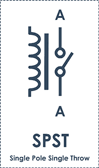
SPST (Single Pole Single Throw) relays have two terminals that can be connected or disconnected and two more for the coil. In total, there are four terminals. It can only regulate one circuit at a time, and it can either open or close it.
- SPDT
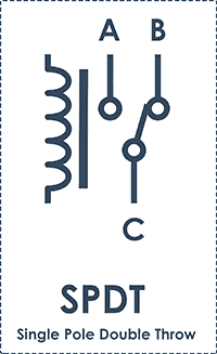
In this type of relays (Single Pole Double Throw), a common terminal connects to either of two other terminals and two more terminals for the coil. Because of its single-pole design, it can only control one circuit at a time, but it has two throw locations to conduct. When one circuit is turned on, the other is turned off, and vice versa.
- DPST
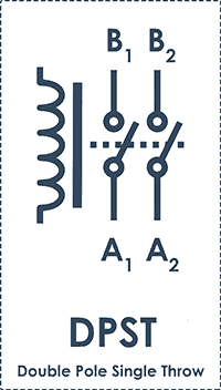
There are six terminals on this type of relay (Double Pole Single Throw). This is the same as having two SPST relays controlled by a single coil. Two entirely separated circuits can be controlled by the double pole. There is only one position for a single throw. As a result, a DPST relay can switch two circuits at the same time by providing a close or open circuit.
- DPDT
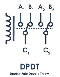
There are eight terminals on this relay (Double Pole Double Throw). These have two change-over terminals, which is the same as having two SPDT relays controlled by a single coil. Double pole and double throw refer to the fact that it can control two circuits and conduct in two different directions.
Types of Relay
Based on the principle of construction and function, there are different types of relays categorized as
- Electromechanical relay (EMR)
Electromechanical relays are the ideal choice for controlling many circuits with a single trigger pulse. Electromechanical relays feature switch contacts that are mechanically opened and closed to turn ON/OFF using electromagnetic force. It has the benefit of requiring less resistance to switch current and doesn’t need a heat sink. They are also less resistant to electric shock and fail-safe. The only drawback to EMR is that it wears out quickly.
- Solid State Relay (SSRs)
Solid-state relays offer the advantage of not having mechanical moving components over electromechanical relays. Rather, they are made up of semiconductors and electronic components like optocouplers. Solid-state relays use electronic circuits to turn on/off signals, currents, or voltages. A solid-state relay, often known as a MOSFET relay, operates on the same concept as a basic switch. With the help of a MOSFET transistor, the load connected to the relay circuit will quickly turn on and off when power is given to one terminal and a control signal is transmitted through another terminal. When the relay is in the off state, the current is blocked, but when a control signal is activated, the current is allowed.
Both AC and DC switching applications employ SSRs. DC relays utilize a single MOSFET transistor to drive current in both directions, whereas AC relays use two MOSFET transistors to drive current in both directions (positive half cycle and negative half cycle).
- Microprocessor/Numerical relay
Microprocessor-based relays are used for switching. Software testing methods and diagnostics communication, among other things, are used to detect electrical defects. The microprocessor monitors voltage and current, as well as frequencies, ground faults, and power loss due to excitation.
Advantages of Relay
- Let’s start with the advantages of a relay.
- It allows us to control a remote device. It is not necessary to be near the device to make it work.
- Change contacts easily.
- Isolates the activating part of the actuating part.
- It works well at high temperatures.
- It is activated with low current, however, it can activate large machines of great power.
- With a single signal, you can control several contacts at once.
- It can switch direct current or alternating current.
Disadvantages of Relay
- Contacts are damaged over time and continuous use (wear, oxidation, etc.)
- They generate a lot of noise with the activation and deactivation of the contacts.
- Switching time is high
Relay Applications
The following are some of the most common relay applications in the automation, energy, smart grid, telecom, and power industries.
- Used for ON/OFF applications
- Capable of switching multiple circuits
- Coil relays are used for the protection of circuits
- Controls high power circuit with a low power signal
- For home appliances such as refrigerators, washing machines
- For molding equipment, packing machinery, vending machines
- They are used in Motor & lighting control
- Used in Aerospace, Defense, and automotive industries
- Used in the traffic signal controllers, temperature controllers, heaters
- When the supply voltage is other than the rated voltage, a set of relays sense the voltage variations and control the load circuit with the help of circuit breakers.
- Solid-state relays use power semiconductor devices such as transistors and thyristors to switch currents up to 100 amps.
- Prevention of non-directional overcurrent protection and direction control of earth faults.
Hope this blog helps you to understand what a relay is? Its construction, working, configurations, advantages and disadvantages, and applications. We, MATHAELECTRONICS will come back with more informative blogs.