
DC to DC Converter with Constant Current (CC) and Constant Voltage (CV) Control – Schematics, PCB, Parts List, and Working
In this article, we will be learning about the features and working of the XL4015 which is a 5A 180KHz 36V Buck DC to DC Converter.

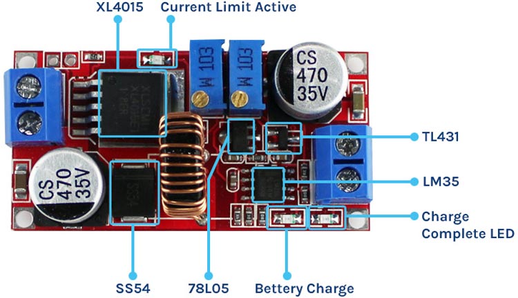
XL4015 DC DC Buck Converter Module
Here we will desolder all the components from the module, completely reverse engineer the schematic and make the PCB from it, so that we can order the components and make the PCB ourselves. In addition, we’ll test the module and compare all the datasheet parameters to see if they hold true or not. So without further ado let’s get right into it.
XL4015 DC-DC Buck Converter Module
There are numerous situations in which the constant current and constant voltage converters come in handy; one such application is charging a lithium battery at a constant current using this module with ease. It’s also a good idea to use a constant current when you’re testing a circuit for the first time, so that any mistakes you might have made in the build process can be minimised.

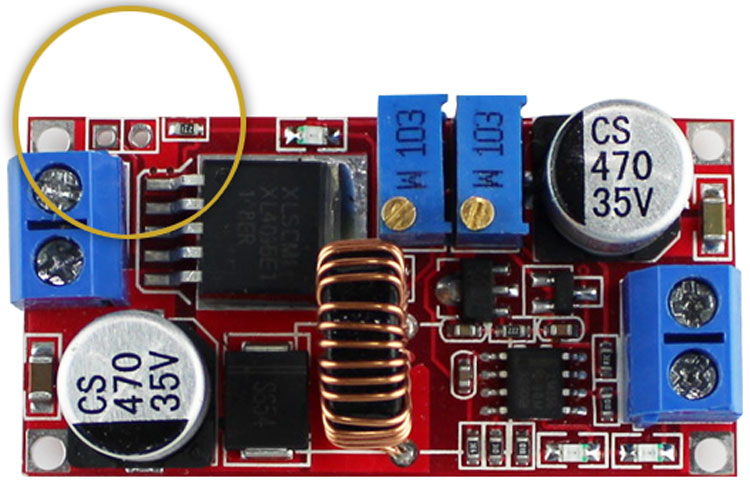
You can see in the image above that we have a DC input connector for connecting to an unregulated power supply. The constant current and voltage are then set using two 10K potentiometers.
Aside from that, the board has three LED indicators: one near the input connector shows when the module is in constant current mode, while the other two near the output are primarily used to charge batteries (battery charging and battery full indicators). Its input voltage ranges from 8V to 36V and its output voltage ranges from 1.25V to 32V, among other things.
The device’s PWM can reach 100% duty cycle and 180 kHz operating frequency at full load. The module has a 5A output current and can operate at up to 96 percent efficiency. Thermal shutdown, short circuit protection, and current limit are all included in the device’s safety features.
Components used in DC-DC Buck Converter
To get started, here is a list of the components needed to build the XL4015 Buck Converter Circuit. There is a buck converter IC called XL4015 on this board, which is a 5pin IC designed and developed by XLSEMI, a well-known manufacturer in China and known for producing compact buck and boost converters. To build the 5A Buck Converter Circuit, you’ll need the following components:
- XL4015 Buck Converter IC – 1
- 78L05 Voltage Regulator – 1
- LM358 op-amp – 1
- SS54 Schottky Diode- 1
- TL431 Programmable Reference – 1
- 470uF,35V Capacitor – 2
- 10uF 0805 Capacitor -2
- 10K Ten Turns Trim Pot – 2
- 0.1uF Capacitor – 3
- 270R Resistor – 1
- 1K Resistor – 2
- 2.2K Resistor – 1
- 10K Resistor – 1
- 71.5K Resistor – 1
- 90.9K Resistor – 1
- LED 0805 – 3
- Screw Terminal – 2
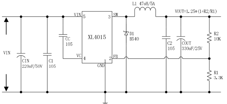
Circuit Diagram of the XL4015 5A Buck Converter
At the same time, the circuit is both simple and difficult. The typical application schematic for the XL4015 5A buck converter Module can be found in the datasheet.

The schematic for the buck regulator portion of our schematic is very similar to that of the above schematic, with the only difference being that it has additional current limiting capabilities.
Understanding how current limiting functions work is important now. As you can see in the schematic, the TL431 IC is powered by a 78L05 Voltage Regulator, which is an ultra-low-power regulator. A 71.5K resistor and a potentiometer are used to set the TL431 reference to a constant current regulator mode. Using this voltage as a reference, the current through the resistor is limited. The op-amps are supplied with a constant current via the TL431 circuit shown below.

The first op-amp in the circuit serves to limit the flow of current through the circuit. The output sense voltage is compared to the TL431 IC’s reference voltage in this section. If the output sense voltage is higher than the reference voltage, the op-output amp’s goes high, and the IC’s output is shut off by the circuit’s shutdown function.

This image shows you an application circuit from the datasheet alongside a more practical circuit. A diode is used as a reverse current blocker in the practical circuit, but a light emitting diode (LED) is used instead because it also lights up when the current limit function is active.

The last part of the circuit is used to show whether or not the battery is charging or is fully charged. When the battery is fully charged in this circuit, the output drops to a low level, causing the charging complete LED to illuminate. This LED illuminates when the battery is charging.
Recreating the PCB for XL4015 Buck Converter
The datasheet’s application circuit is shown in this image, as well as a more practical circuit. To prevent reverse current flow in the practical circuit, a diode is used. However, LEDs are preferred because they also serve as current limit indicators.

Eagle’s “Manufacturing” feature can be used for this purpose, and what we’ve come up with so far looks like this:
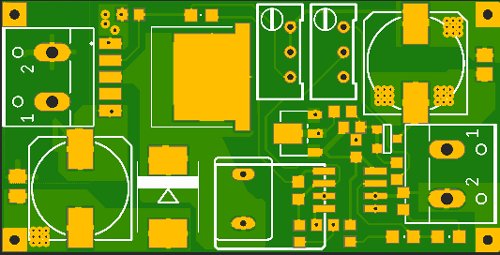
PCB’s TOP and BOTTOM sides can be seen in the images above and below, respectively-

The PCB part of the project is complete, and the Gerber file for the project can be downloaded by clicking the given download link.
Testing the XL4015 DC-DC Buck Converter Module
Once the buck converter module has been connected, we then connect it to a DC load with a constant current draw of 1A and begin testing.
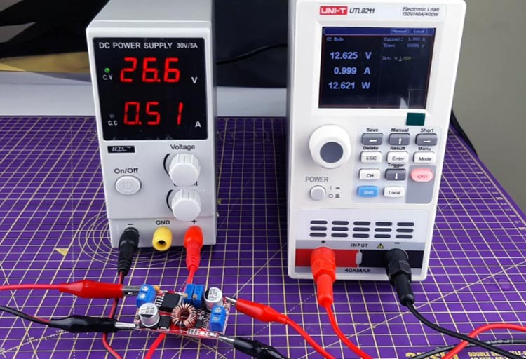
We then increased the constant current to 5A per the datasheet’s recommendation.
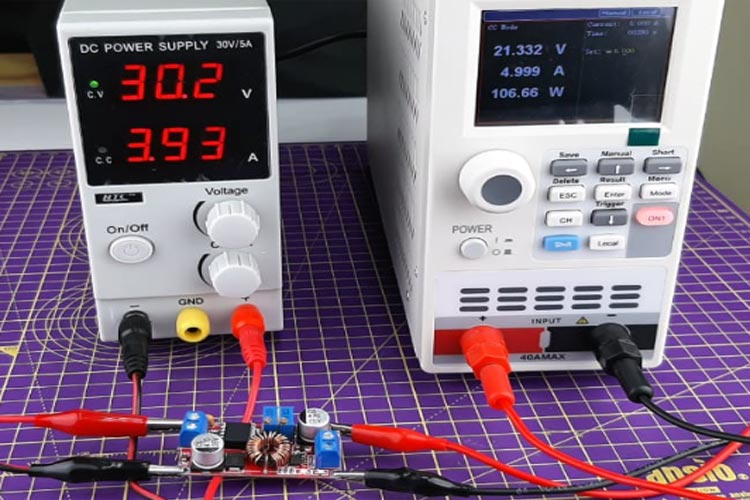
A constant current of 5A was a pleasant surprise considering the module’s small size. I ran this circuit for about five minutes and it worked perfectly.
After that, we checked to see if there were any shorts in the circuit. We also verified that it had short circuit protection built in, as it was advertised on the datasheet. It also worked flawlessly.
Problems Encountered while testing the Buck Converter Circuit
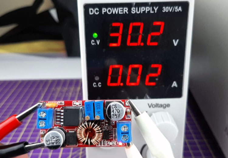
While testing the circuit we encountered a major problem in some of these modules. At the time of writing the article, we had 10 modules in our lab but some of those were working, and some of those were not. This made us very confused.
However, the solution to this issue was incredibly straightforward: we simply connected a 1uF capacitor to the PCB, and the module worked flawlessly thereafter. Other than that, the module board was in perfect working order.
Conclusion
I hope all of you have understood the basics of DC to DC Converter with Constant Current (CC) and Constant Voltage (CV) Control – Schematics, PCB, Parts List, and Working. We MATHA ELECTRONICS will be back soon with more informative blogs soon.
Great writeup! Can I ask what the issue was with the flawed modules, and how/where you added the 1uF capacitor to the pcb to fix it? Thank you!