
Wireless Electricity Charger
Smartphone batteries have a short lifespan and charging cables that break after a few months of use is a nuisance. Wireless chargers are a practical alternative; you simply set them up and forget about them. But how precisely does it operate? Although wireless charging may appear to be a new innovation, its roots trace back more than a century to the Serbian-American inventor Nikola Tesla. Here we design a Wireless Electricity Charger to overcome these issues.
Working Principle
Nikola Tesla successfully carried electricity via the air in the late 1800s. In order to power light bulbs in his New York City laboratory, he utilized resonant-inductive coupling, which creates a magnetic field between a transmitter (which delivers electricity) and a receiver (which receives the electricity).
A few years later, he patented the Tesla coil, a tower topped by a coil that shot electrical bolts. Tesla envisioned a wireless power infrastructure on a much grander scale, but these aspirations were never realized.
The same fundamental idea applies to smartphone wireless charging as it does to inductive charging.
Bill of Material:
| COMPONENT NAME | DESCRIPTION |
| 0.3 – 0.4mm Enamelled Copper wire | For Transmitter & Receiver Coils |
| Resistor 1K | For current limiting |
| Transistor BC-547 | For Switching |
| LED | For Half Rectifier |
| USB Cable | For Charging mobile |
| 9V battery with connector | For the Transmitter power supply |
- You can use Stepdown Transformer (230/5V-1A) with a DC rectifier also.
Design Procedure:
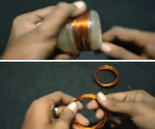
- Designing the Transmitter and Receiving coil
Here, I’ve used an 8cm diameter plastic bottle to make a coil. For coil-like shapes, PVC pipe or any other material can be used. Over the material, 15 turns of enameled copper wire were wrapped. After 15 turns, the copper wire must be terminated and rewound with 15 turns (like Centre Tapped Transformer).
For Receiving coil, likewise, Make it by winding 15 turns of enameled copper wire.
Step 2: Connections
Now that the connections are complete, the oscillator in my design is a BC547 NPN transistor. Transistor TTC5200 can yield superior outcomes.
Connect the base of the transistor to a 1K resistor for current restriction. The center-tapped coil is linked to the battery’s positive terminal and the emitter terminal of the transistor. Through a current-limiting resistor, the other two ends of the transmitter coil are linked to the collector and base terminals of the transistor.
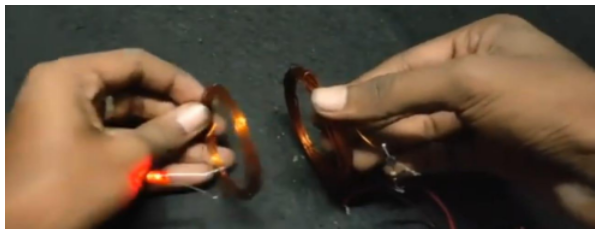
LEDs connect the receiving coil ends to the USB cord (Here LED is used for indication and half-wave rectifier purposes).
Circuit Diagram:

Circuit Diagram for Wireless Electricity Charger
Step 3: Principle of Working
The Transmitter coil is connected to the battery via the Transistor, which converts DC current to frequency (Oscillating circuit). The oscillating current within the transmitting coil causes the coil to emit a magnetic field at a frequency of 1 MHz. This magnetic field oscillation creates an electric current in the receiving coil. The induced current is an alternating current, so it must be converted to a direct current for usage in mobile charging applications. For indication and rectification, I employed LEDs.
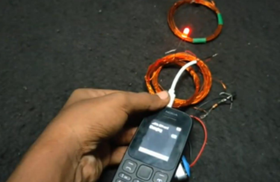
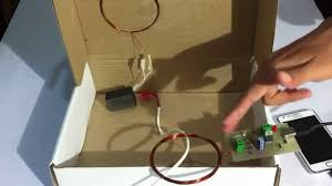
Prototype for Wireless Electricity Charger
Conclusion
Hope this blog helps you to understand how to build a Wireless Electricity Charger. We, MATHA ELECTRONICS will come back with more informative blogs.