
How To Get Started With Raspberry Pi Pico
Our focus in this tutorial is the Raspberry Pi Pico, a Microcontroller board based on the RP2040 Microcontroller released by the Raspberry Pi Foundation. We’ll study the Raspberry Pi Pico Board’s design and layout, as well as the RP2040 Microcontroller’s features and specifications.

Introduction
Raspberry Pi boards have rapidly become an essential resource for anyone interested in computer science, robotics, electronics, or hobbyism. The Raspberry Pi Computer has become an integral part of the modern DIY Community due to its wide availability of both hardware (in the form of plug-in modules, cameras, HATs, etc.) and software (operating systems, libraries, etc.).
But what if you only need to connect a few sensors, activate a few lights, and command a few motors? A Raspberry Pi Computer, which can be purchased for less than $40, is an excessive solution for this need.
These tasks are ideal for microcontroller boards such as the Arduino, STM32 Blue Pill, or ESP32. Embedded systems today are powered by microcontrollers because of their excellent cost-to-performance ratio.
The Raspberry Pi Foundation designed the RP2040, a Dual Core ARM Cortex-M0+ Microcontroller, with this goal in mind. The Raspberry Pi Pico, a $4 Microcontroller Development Board for RP2040, was also unveiled, and it is based on this microcontroller.
RP2040 Microcontroller
The RP2040 Microcontroller is the primary focus of this first lesson. In the past, Broadcom Processors were used in all Raspberry Pi boards (BCM2835, BCM2836, BCM2711, etc.).
They are fully functional application processors that can run a full desktop OS (usually, Linux based).

Contrarily, the Raspberry Pi Pico includes the RP2040 Microcontroller, the first piece of custom silicon developed by the Raspberry Pi Foundation. Yes. What you read is correct. The Raspberry Pi Microcontroller is a product of the Raspberry Pi Foundation, a company best known for its Single Board Computers.
The RP2040 is built on a 40 nm node and features dual ARM Cortex-M0+ cores running at up to 133 MHz. It’s perfect for novices and hobbyists thanks to its plentiful on-chip memory, extensive collection of frequently used peripherals, and special Programmable I/O (PIO) block.
The Raspberry Pi Foundation has additionally supplied top-notch documentation for the RP2040 and the Raspberry Pi Pico Board. What’s more, you can choose between Python and C as the programming language, which adds a new layer of fun.
The MicroPython Port and UF2 Bootloader in ROM of the RP2040 MCU make it simple to upload the code
Important Specifications
Specifications and features of the RP2040 Microcontroller are outlined below.
- Dual ARM Cortex-M0+ Cores
- Clock frequency up to 133 MHz
- 264 KB of embedded SRAM
- 30 GPIO Pins
- Up to 16 MB of off-chip Flash Memory
- 4 channel ADC with 12-bit resolution
- Programmable IO
- Other Peripherals – 2 UARTs, 2 SPI Controllers, 2 I2C Controllers, 16 PWM Channels, USB 1.1 Controller and PHY
RP2040
The origin of the name “RP2040” is fascinating. “RP” denotes a Raspberry Pi computer. Next, we have a string of four digits. Let’s break down what all these numbers mean. Using the year 2040 as an example, I am counting from 2 as the first digit, then 0 as the second digit, and so on.
- Number 1: indicates how many processor cores are available. Due to the fact that it is a dual-core microcontroller, the answer is 2.
- Number 2:indicates the processor’s core architecture. The ARM Cortex-M0+ processor is used here. Therefore, we have a value of zero.
- Number 3: represents the amount of RAM found directly on the chip. This number can be calculated as follows: floor (log2 (ram / 16k)). The formula yields a value of 4 because RP2040 has 264 KB of RAM.
- Number 4: Represents On-Chip Flash (Non-Volatile Storage). This is calculated as floor (log2 (non-volatile / 16k)). A value of 0 indicates the absence of any on-chip non-volatile storage.

Introduction to Raspberry Pi Pico
After this brief review of the RP2040 microcontroller, we’ll investigate the Raspberry Pi Pico. It’s the most recent product release from the Raspberry Pi Foundation. The Raspberry Pi Pico is an affordable development board for the company’s RP2040 Microcontroller.
The Raspberry Pi Pico is not a replacement for the original Raspberry Pi boards. However, the former is a Microcontroller Development Board and the latter is a family of Single Board Computers (SBC).
A standard Raspberry Pi can be used for a wide variety of purposes, including web browsing, document and video editing, media playback, and even gaming. However, these are beyond the capabilities of a Raspberry Pi Pico. As a microcontroller development board, it can be used in a wide variety of physical computing applications, from sensor interfacing and LED manipulation to motor play and control.
Features of Raspberry Pi Pico
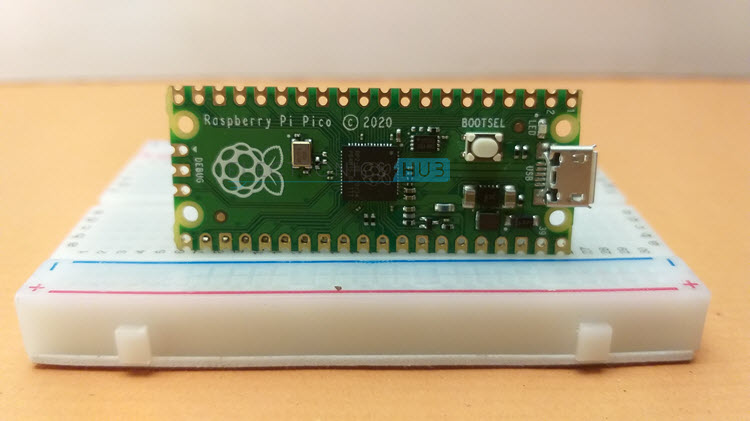
The Pico is essentially just a printed circuit board (PCB) with a microcontroller, micro-USB port, and a few other critical components and castellated edges. This board can be soldered on top of another PCB thanks to its printed circuit board (PCB) and edge castellations. In what way is this helpful?
Let’s say you’ve decided to use the RP2040 microcontroller in your product design. Using a bare microcontroller chip in your hardware means you’ll need to figure out how to power it, set the time, connect it to a computer, and so on. This is required at a bare minimum for RP2040 to function.
You can use the Pico as a baseboard for your hardware and focus on designing the most crucial part of the application, such as an LED Control Circuit or a Motor Driver Circuit, since the Pico already has all the necessary circuitry on-board. In addition to decreasing the time it takes to get your product to market, this method also requires less work from hardware engineers.
Other important features of Pico are:
- RP2040 Microcontroller
- 2 MB of SPI Flash
- Type B Micro-USB port for power and programming
- 40 DIP style IO Pins with edge castellations
- 3-pin ARM Serial Wire Debug (SWD) interface
- 12 MHz Crystal oscillator
- Boot Selection Button
- One user LED (connected to GPIO 25)
- 3.3V Fixed Output Buck-Boost SMPS Converter
Board Layout
The Raspberry Pi Pico Board’s design is depicted in the following image. The 40 IO pins, instead of coming with headers, have holes for us to solder on our own. These 40 Pins and 3 Debug Pins also feature castellated edges.
These edges make it easy to solder the Pico onto a breakout board you’ve designed.
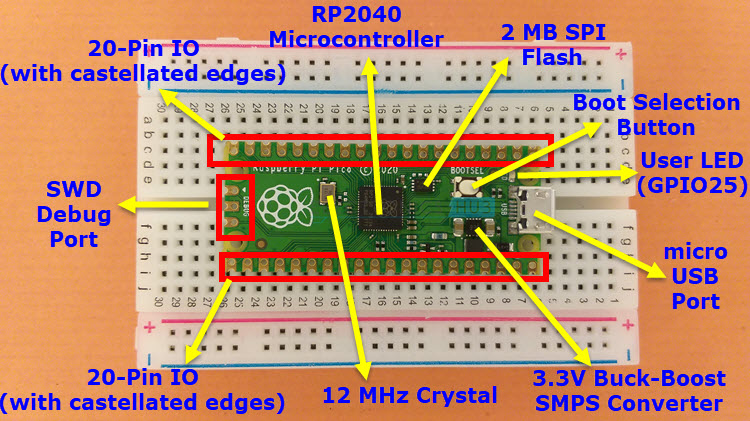
A second (somewhat vexing) fact is that the Pico has no labelling for its pins on its top. They can be found on the underside of the board. Thus, it is essential to keep a visual representation of the Raspberry Pi Pico Pinout Diagram on hand.
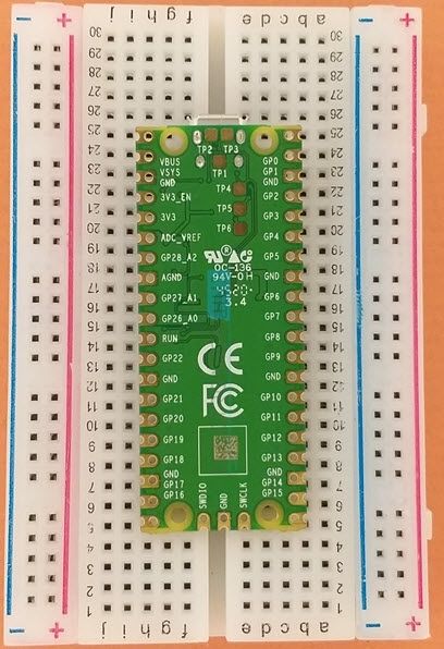
Raspberry Pi Pico Pinout
In the following image, you’ll find a complete Raspberry Pi Pico Pinout. There are a total of 40 pins on the Pico (20 on each long edge), 26 of which are IO Pins, and 14 that are related to power and the system. In addition to these 40 pins, SWD Debugging also makes use of the additional 3.

Testing MicroPython on Raspberry Pi Pico
Let’s give the Raspberry Pi Pico a whirl by installing the MicroPython firmware and coding up a quick Blinky Python programme. Simply putting the new Raspberry Pi Pico Board through its paces in MicroPython testing.
As such, I plan to write some introductory guides to using MicroPython on the Pico board.
Since the Pico has an integrated LED, I did not feel the need to solder the IO header at this time (connected to GPIO 25). I am also using a Raspberry Pi to write code for Pico. But we’re not limited to any particular OS.
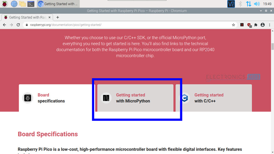
Download MicroPython
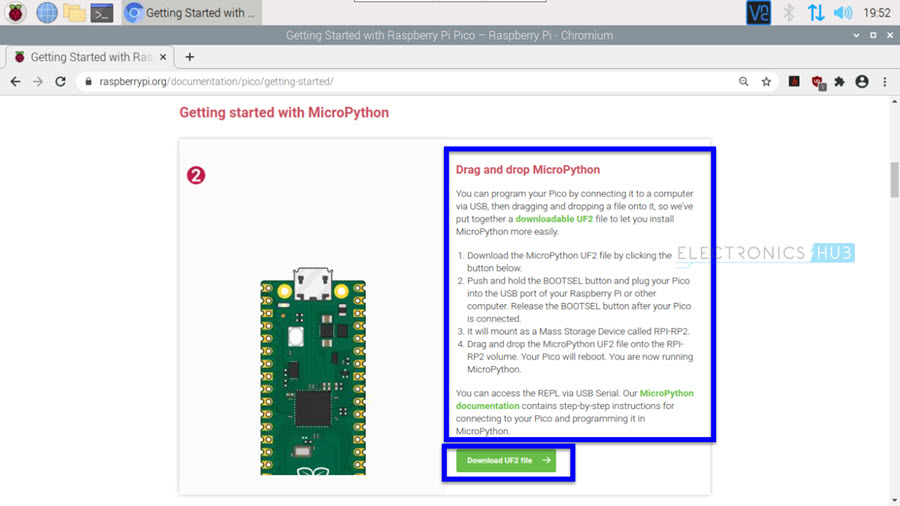
Start by firing up your preferred web browser and navigating to the Raspberry Pi Pico official Getting Started page. A link to “Getting Started with MicroPython” is available. All it takes is a click.
Here’s an animated guide on what to do next. After reading the guide in its entirety, select the “Download UF2 File” button.
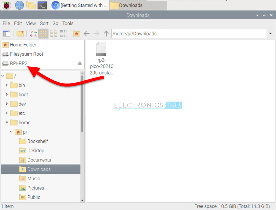
A file with the extension.uf2 is obtained. This is the difficult (and infuriating) part. Put the Pico’s micro-USB cable into it first. You should not connect the USB cable’s other end to the computer (or Raspberry Pi) just yet.
Putting the Pico into USB Flash Mode requires both pressing and holding the BOOTSEL button, as well as connecting the device via USB to a computer. If all goes well, the Pico will show up as a “RPI-RP2” mass storage device.

Simply transfer the MicroPython Firmware.uf2 file from your computer’s downloads folder to the Pico by dragging and dropping the file. There will be no more Picos. You are now prepared to begin programming in Python.
Thonny Python IDE
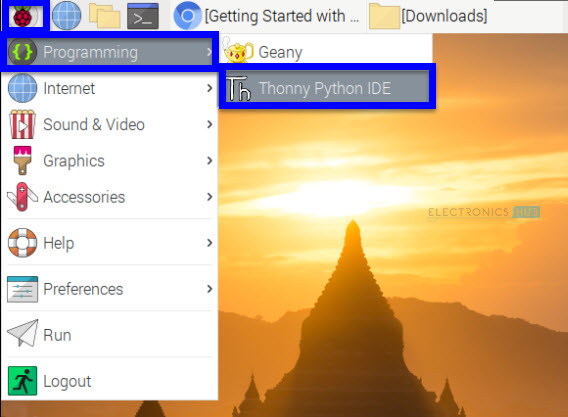
To access the software library, select the Raspberry icon located in the upper left. Click the Programming menu item to launch the Thonny Python integrated development environment.
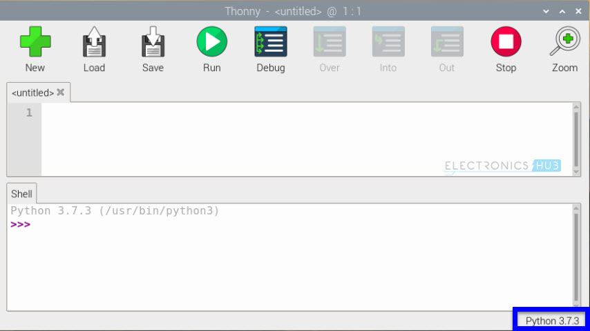
The first step in using Thonny is to choose the Python Interpreter. The default choice of Python version for the interpreter is the latest stable release (3.x.x). However, since MicroPython is what we need to get up and running on our Pico, we’ll need to select the “Python 3.7.3” option in Thonny’s lower right corner.
A list of translators will be provided to you. Choose the MicroPython (PiCo) option for the Raspberry Pi. So long. Congratulations! You are now prepared to programme your Pico using Python.

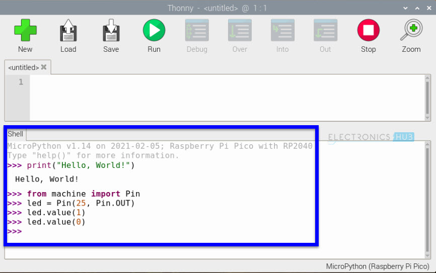
Enter the following into the Shell at the bottom of the page.
print(“Hello, World!”)
This is an instruction for your Pico’s MicroPython interpreter. As soon as it receives the instruction, it will print out the text as a response.

Let’s move on to powering the onboard LED up and down. The on-chip hardware will be managed via the “machine” module of the MicroPython Port. The Pin class is used to manage GPIOs in the machine module. There’s an LED on board, and we know that it’s linked to GPIO 25.
The Shell prompt will look like this when you have entered the lines below.
from machine import Pin
led = Pin(25, Pin.OUT)
led.value(1)
led.value(0)
The led.value(1) will make the GPIO 25 HIGH and led.value(0) will make the GPIO 25 LOW.
Conclusion
I hope all of you had understand the basics of how to get started with Raspberry Pico. We MATHA ELECTRONICS will be back soon with more informative blogs.