
How to use I2C Communication on Arduino
This guide will show you how to use I2C Communication with an Arduino. This Arduino I2C tutorial covers configuring the Master and Slave boards, using the I2C pins, and demonstrating I2C communication between two Arduino UNO boards.
What is I2C?
Inter-Integrated Circuit (I2C) is a Phillips-developed synchronous serial communication protocol for exchanging data between a fast microcontroller and slower peripherals (such as memory or sensors) over a single pair of wires. That’s why you might also hear it referred to as “TWI” (Two Wire Interface).
I2C allows for data transfer rates of 100 kbit/s (clock 100 kHz – Standard Mode), 400 kbit/s (clock 400 kHz – Fast Mode), 1 Mbit/s (clock 1 MHz – Fast Mode Plus), and 3.4 Mbit/s (clock 3.4 MHz – High Speed Mode).
The distances involved are small enough that sensors, memories, and displays can be interfaced.
I2C Bus
Serial Data (SDA) and Serial Clock (SCL) are the two wires that make up the I2C Bus (SCL). The SDA line is used for data transmission, while the SCL line is for synchronising devices to the clock signal.
As open-drain drivers, both of these bus lines require pull-up resistors to remain in the HIGH state.

I2C Bus devices can be either “Master” or “Slave,” depending on their connection type. It is the job of the Bus Master to transmit and receive data to and from the slave devices. The master also provides the clock signal.
It is possible to have both multiple masters and multiple slaves on an I2C network (but we usually see single master and multiple slaves). There is a unique 7-bit address for each slave device on the I2C bus.
Using this address, the master can choose a specific slave to send or receive data from, and the slave will respond appropriately.
I2C in Arduino
I2C communication is supported by Arduino. Analog Input pins A4 and A5 have the additional function of I2C, as detailed in the “ARDUINO UNO PINOUT” tutorial for the Arduino UNO.
To communicate with other devices using SDA and SCL, use the A4 and A5 pins, respectively. The original Arduino UNO’s revision 3 added SDA and SCL pins near Digital IO Pin 13 (near the USB socket).
The following table summarises the I2C pin configurations of the most common Arduino boards and should prove useful if you’re working with a different board.
| Board | SDA and SCL Pins |
| Arduino UNO | A4 and A5 |
| Arduino Nano | A4 and A5 |
| Arduino Mega 2560 | 20 and 21 |
| Arduino Micro | 2 and 3 |
| Arduino Leonardo | 2 and 3 |
The ATmega328P microcontroller found in the Arduino UNO and Nano is capable of I2C data transfer rates of up to 400 kilohertz.
How to use Arduino I2C Interface?
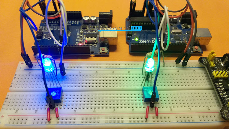
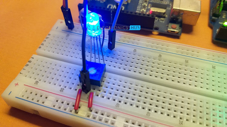
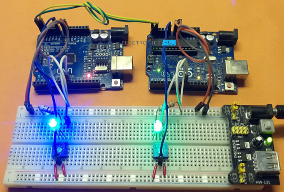
Let’s construct a simple circuit to show how I2C in Arduino works. For this demonstration, I used an I2C connection between two Arduino UNO boards. I threw in some LEDs and potentiometers to make things more interactive and clear how the data was being transmitted (one set for each UNO Board).
Analog Input pins (A0) are used to connect the potentiometers, while a Digital Input Output (IO) pin capable of Pulse Width Modulation (PWM) is used to power the LEDs (Pin 9). The first UNO board acts as the I2C Bus Master, while the second UNO is set up to function as a Slave.
When I turn the potentiometer that’s connected to the Master Arduino UNO, the digital value between 0 and 1023 is read, mapped to a suitable PWM value between 0 and 255, and sent over the I2C Bus to the Slave Arduino.
After receiving the PWM Value, the Slave Arduino modifies the intensity of its LED. The Slave Arduino also communicates with Master Arduino by sending its own potentiometer value in PWM format (up on request from the Master).
The LED intensity is then changed based on the PWM value read from the Slave Arduino by Master Arduino. Over the I2C Bus, this conversation effortlessly resumes and continues.

Just for learning the basics of Arduino I2C Communication, here is a short and easy circuit. The circuit can be altered to accommodate a wide variety of slave devices on an I2C bus, including an I2C LCD, EEPROM IC, BMP180 Barometric Pressure Sensor, and more (a weather station with data logging).
Components Required
- Arduino UNO x 2
- 10 kΩ Potentiometer x 2
- 5mm LED x 2
- 330Ω Resistor x 2
- Breadboard
- Connecting Wires
- Breadboard Power Supply (optional)
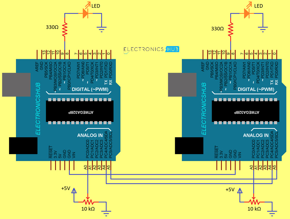
Circuit Diagram
The following picture is a circuit diagram for a demonstration using two Arduino UNO boards connected via the I2C protocol.
Code
Arduino’s I2C peripheral necessitates familiarity with the Wire library. Here you’ll find the primary library for using the I2C Bus to talk to TWI and I2C devices (SDA and SCL lines).
Wire Library
There’s no need to go looking for the Arduino IDE online because it’s already included. To use I2C with Arduino, just import the Wire library.
#include <Wire.h>
If you’re making an app that uses the I2C bus, the Wire library has you covered with 10 pre-written functions. These items are:
- Wire.begin()
- Wire.requestFrom()
- Wire.beginTransmission()
- Wire.endTransmission()
- Wire.write()
- Wire.available()
- Wire.read()
- Wire.SetClock()
- Wire.onReceive()
- Wire.onRequest()
Send data to the slave device at the given address using this function.
Wire Library Functions
Wire.begin()
Once you’ve initiated transmission with the aforementioned function, you can begin sending data with Wire.write().
When the master is using Wire, you can also use this function to have data written from the slave to the master.
- Wire.begin() – Master
- Wire.begin(address) – Slave
Wire.beginTransmission(address)
Send data to the slave device at the given address using this function.
Wire.write()
Once you’ve initiated transmission with the aforementioned function, you can begin sending data with Wire.write().
When the master is using Wire, you can also use this function to have data written from the slave to the master.
- Wire.write(value) – Send a single Byte value
- Wire.write(string) – Send a series of Bytes in the form of string
- Wire.write(data, length) – Send an array of data of specified length
Wire.endTransmission()
Once you’ve initiated transmission with the aforementioned function, you can begin sending data with Wire.write().
Wire.read()
When the master is using Wire, you can also use this function to have data written from the slave to the master.
| Wire.requestFrom() |
Master I2C Device uses this function to request bytes of data from a slave device. Use the Wire.read() function to retrieve the data.
- Wire.requestFrom(address, quantity) – Request a number of bytes of data mentioned by quantity from a slave device with an address specified in the address field.
Wire.onReceive()
This is a handler function used to define a function which is called when Slave receives data from Master.
Wire.onRequest()
This is a handler function used to define a function which is called when Master requests data from slave.
Master Code
Using the above-mentioned functions, I wrote a simple code for Master Arduino to send the PWM value and also request a byte of data from the Slave.
| /*Arduino Master I2C*/ | |
| #include <Wire.h> | |
| #define ledPin 9 | |
| byte rcvData; | |
| int potValue; | |
| void setup() | |
| { | |
| Wire.begin(); | |
| rcvData = 255; | |
| pinMode(ledPin, OUTPUT); | |
| } | |
| void loop() | |
| { | |
| potValue = analogRead(A0); | |
| potValue = map(potValue, 0, 1023, 0, 255); | |
| Wire.beginTransmission(0x14); | |
| Wire.write(potValue); | |
| Wire.endTransmission(); | |
| Wire.requestFrom(0x14, 1); | |
| if(Wire.available()) | |
| { | |
| rcvData = Wire.read(); | |
| } | |
| analogWrite(ledPin, rcvData); | |
| } |
Slave Code
In the Slave Arduino code, I defined the Slave address as 0x14. It can be any value less than 128. An important point to note about ArduinoI2C Wire Library I that it uses 7-bit I2C Address without the Read / Write bit.
So, if you have an 8-bit address (which includes the R / W bit), right shift the address by 1 and then use it in the Wire Library. The library will automatically adjust the address depending on the Read or Write operation.
Also, make sure that the slave’s address is unique and that no two slaves should have the same address.
When data is received by the slave or requested from the slave, the functions I named “DataReceive” and “DataRequest” are invoked. The data received by the Slave in the DataReceive function contains the PWM value sent by the Master.
The PWM value from the Slave must be sent to the Master via the DataRequest function.
| /*Arduino Slave I2C*/ | |
| #include <Wire.h> | |
| #define ledPin 9 | |
| byte rcvData; | |
| int potValue; | |
| void setup() | |
| { | |
| Wire.begin(0x14); | |
| /*Event Handlers*/ | |
| Wire.onReceive(DataReceive); | |
| Wire.onRequest(DataRequest); | |
| rcvData = 255; | |
| pinMode(ledPin, OUTPUT); | |
| } | |
| void loop() | |
| { | |
| potValue = analogRead(A0); | |
| potValue = map(potValue, 0, 1023, 0, 255); | |
| analogWrite(ledPin, rcvData); | |
| } | |
| void DataReceive(int numBytes) | |
| { | |
| while(Wire.available()) | |
| { | |
| rcvData = Wire.read(); | |
| } | |
| } | |
| void DataRequest() | |
| { | |
| Wire.write(potValue); | |
| } |
Conclusion
I hope all of you had understand the basics of a beginner’s guide for programming Raspberry Pi Pico in windows. We MATHA ELECTRONICS will be back soon with more informative blogs.