
Infrared technology is employed in everyday life as well as in industry for a variety of purposes. The key advantages of IR sensors are their low power consumption, simple construction, and useful functionality. IR signals are undetectable to the naked eye. In the electromagnetic spectrum, IR radiation can be found in the visible and microwave ranges.
Wavelengths of these waves typically range from 0.7 m to 1000 m. Near-infrared, mid-infrared, and far-infrared are the three sections of the IR spectrum. The wavelength extends from 0.75 to 3 meters in the near-infrared region, 3 to 6 meters in the mid-infrared region, and more than 6 meters in the far IR zone. This blog will be talking about the interfacing of IR sensors with Arduino Board & Raspberry Pi Board.
What is an IR Sensor/Infrared Sensor?
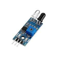
An infrared sensor is an electrical sensor that detects and measures infrared light emitted by an object or its surroundings. The IR sensor emits or detects infrared radiation to identify certain features in its surroundings. These sensors can also detect or measure a target’s heat as well as its motion. The IR sensor circuit is a critical component in many electronic devices.
This IR sensor consists of two parts, a Transmitter, and a Receiver. The transmitter emits IR light, and the object reflects that light. The photodiode (receiver) receives the reflected light. The amount of reflection and reception varies with distance. These differences cause a change in the input and are thus used for proximity detection. IR LED sensor module has both the transmitter and emitter designed to work on the 940 nm wavelength.

A typical infrared detection system consists of five fundamental components: an infrared source, a transmission channel, an optical component, infrared detectors or receivers, and signal processing. Infrared sources include infrared lasers and infrared LEDs with specified wavelengths.
Vacuum, atmosphere, and optical fibers are the three basic types of media utilized for infrared transmission. Optical components are used to focus or limit the spectrum response of infrared radiation.
Specifications:
- The operating voltage is 5VDC
- I/O pins – 3.3V & 5V
- Mounting hole
- The range is up to 20 centimeters
- The supply current is 20mA
- The range of sensing is adjustable
- Fixed ambient light sensor
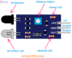
IR Sensor Module Pins:
- +5v Source: IR sensor Module requires +5v to work perfectly.
- Ground: In order to get operation from the IR Sensor module we need to provide ground to the sensor module.
- OUT Pin: OUT pin is used to connect the sensor with the microcontroller‘s input or output port.
Types of Infrared Sensor
Infrared sensors are classified into two types: Active IR sensors and Passive IR sensors.
- Active IR Sensor
The transmitter and receiver are both included in this active infrared sensor. The light-emitting diode is employed as a source in the majority of applications. A non-imaging infrared sensor is an LED, while an imaging infrared sensor is a laser diode.
These sensors operate on the basis of energy radiation, which is both received and detected. It can also be processed by utilizing a signal processor to retrieve the relevant data. Reflectance and break beam sensors are the best examples of this active infrared sensor.
- Passive IR Sensor
The passive infrared sensor consists only of detectors and does not include a transmitter. These sensors make use of a transmitter or an infrared source. This object generates energy that infrared sensors detect. After that, a signal processor is utilized to decode the signal and extract the necessary data.
They are divided into two categories: quantum and thermal. Infrared radiation is used as a heat source in thermal infrared sensors. Thermal infrared detectors include thermocouples, pyroelectric detectors, and bolometers. Infrared sensors of the quantum kind have a better detection performance. It is faster than infrared detectors of the thermal kind. Quantum type detectors’ light sensitivity is wavelength-dependent.
How Can We Tell That The IR Sensor Is Working or Not?
There are a variety of reasons why the sensor’s output isn’t correct, and I’ve mentioned a few of them below.
- Program Issue
This type of mistake doesn’t occur usually. Still, if the module isn’t operating, examining such minor details will assist. Please double-check that the signal pin is connected to the proper pin.
- Output Gain of 555 Timer IC is Not Adjusted Properly
This is the most common issue; such issues are caused by incorrect gain adjustment of the 555 timer IC, and this problem can be fixed by adjusting the potentiometer installed on the module to its normal setting.
- IR Sensor is Still Not Working
Take out your phone and switch on the camera on this module if you see a red light from the sensor, the module is completely functional and all connections need to be rechecked.
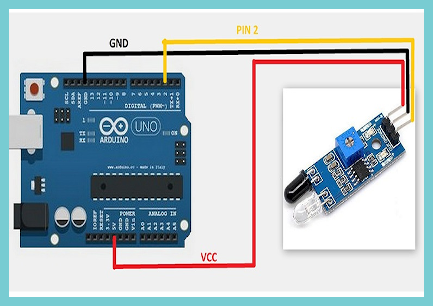
IR Sensor Interfacing With Arduino Board
The interface of the IR sensor with the Arduino Board is shown in the sketch below. We’ve linked the module’s signal pin to the Arduino’s D7 pin and powered it with the VCC and GND pins in this design.
Arduino Code For Infrared Sensor
| int SignalPin = 2; // Connect the signal pin of IR module to the D2 pin of Arduino void setup() { pinMode(SignalPin, INPUT); // Initialize D2 as an INput pin Serial.begin(9600); } int Object = HIGH; void loop() { Object = digitalRead(obstaclePin); if (Object == LOW) { Serial.println(“Object Not Found”); // If there is nothing in its path delay(200); } else { Serial.println(“Obstacle Found”); //If there is obstacle } delay(100); } |
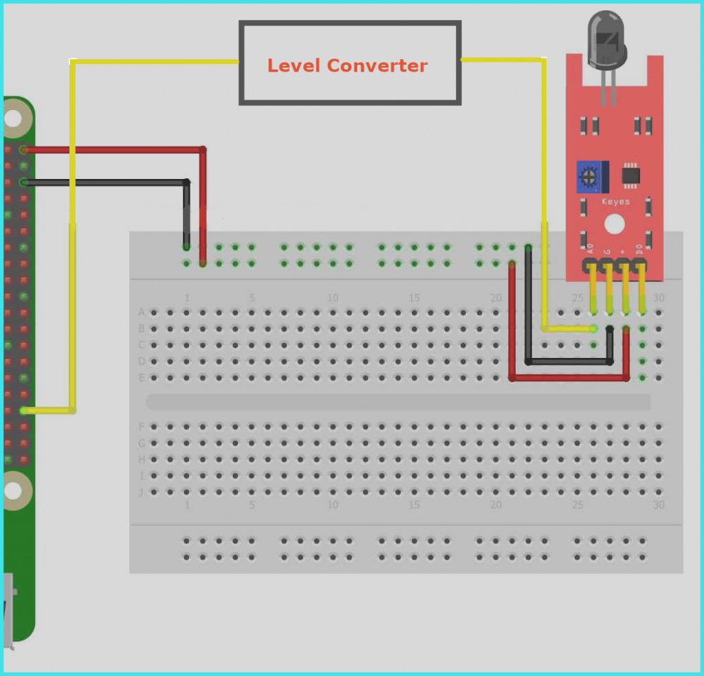
IR Sensor Interfacing With The Raspberry Pi
The connection of the IR sensor with the Raspberry Pi is depicted in the diagram below. We’re powering the IR sensor with the Raspberry Pi and utilizing a level converter between the sensor and the Raspberry board in this diagram. We’re using the level converter because the Raspberry Pi’s GPIO pins can’t tolerate voltages higher than 3.3v. And if we don’t utilize the level converter, the Raspberry Pi board is at risk of being damaged by the high voltage. As a result, I would advise using the level converter.
import RPi.GPIO as GPIO # Import Raspberry Pi GPIO library def button_callback(Detection): print(“Object Is detected”) GPIO.setwarnings(False) # Ignore warning for now GPIO.setmode(GPIO.BOARD) # Use physical pin numbering GPIO.setup(34, GPIO.IN, pull_up_down=GPIO.PUD_DOWN) # Set pin 10 to be an input pin and set initial value to be pulled low (off) GPIO.add_event_detect(10,GPIO.RISING,Detection=Object_detected) # Setup event on pin 10 rising edge GPIO.cleanup() |
Conclusion:
Hope all of you have understood how to interface the IR Sensor with the Arduino & Raspberry Pi. We MATHA ELECTRONICS will be back soon with more informative Blogs.