
I am text block. Click edit button to change this text. Lorem ipsum dolor sit amet, consectetur adipiscing elit. Ut elit tellus, luctus nec ullamcorper mattis, pulvinar dapibus leo.

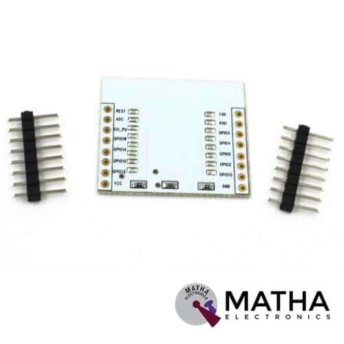
ESP8266 Serial Wifi module Adapter Plate
₹150.00 inc. GST

Heatsink for Raspberry pi 4
Original price was: ₹150.00.₹110.00Current price is: ₹110.00. inc. GST
1.8″ TFT DISPLAY FOR ARDUINO
₹950.00 inc. GST
- Display Size: 1.8″
- Driver IC: ST7735
- Input Voltage (V): 3.3 to 5
- Pixel Resolution: 128 x 160
- Interface Type: SPI
- 18-bit (262,144) colour
- 4 or 5 wire SPI digital interface
- Built-in microSD slot – uses 2 more digital lines5V compatible!
- Use with 3.3V or 5V logic
- On-board 3.3V @ 150mA LDO regulator
- 2 white LED backlight, a transistor connected so you can PWM dim the backlight
- 1×10 header for easy breadboarding
- 4 x 0.9″/2mm mounting holes in corners
- Overall dimensions: 34 x 56 x 6.5mm
- Current draw is based on LED backlight usage: with full backlight draw is ~50mA
Description
In most of the Arduino projects, it would be extremely delighted to have a display through which we can monitor the vitals of our project. 1.8 Inch TFT LCD Touch Screen for Arduino display module designed specifically for Arduino compatible MCU Board. This module adds a touch up to your Arduino project with a beautiful large touchscreen display shield with a built-in microSD card connection. The display can load images from an SD card using the SD card slot present at the back of the device.
This 1.8 Inch TFT LCD designed with a ST7735 coloured TFT display with a resistive touch screen. The ST7735TFT display provides a resolution of 120×160 pixels which can display a wide range of colours ( full 18-bit colour, 262,144 shades!). Thus providing a better display. It offers more resolution than a black and white 128×64 display. The ST7735 controller IC in this 1.8-inch TFT LCD screen supports MCU Interface. It is well-known for its inexpensive price and compact construction. The ST7735 TFT communicates with the master device using the SPI (serial peripheral interface) protocol. The display communicates using the SPI protocol and features its own pixel-addressable frame buffer. This implies that it’s often used with a variety of microcontrollers, and we only require four I/O pins. It also has an SD card slot for storing colourful bitmaps, which may be simply loaded and shown on the screen.
PIN DESCRIPTION:
- RST: reset
- CS : chip select
- D/C: data/command
- DIN: data in
- CLK: clock
- VCC: Power Supply
- BL: backlight
- GND: Ground
Reviews (0)
Shipping & Delivery

Related products


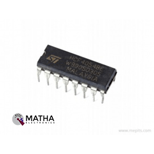
CD4054 4 Segment Liquid Crystal Display Driver IC
- 4 Segment Liquid Crystal Display Driver With Strobed Latch Function
- Supply Voltage Range: 3 to 20V
- Input Current: ±10mA
- Power Dissipation: 200mW
- Low level Output Voltage: 0.05V
- High level Output Voltage Min.: 4.95V
- Low level Input Voltage Max.: 1.5V
- High level Input Voltage Min.: 3.5V
- Propagation Delay Time Max.: 800ns
- Package: DIP-16
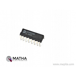
CD4055BE CMOS Liquid Crystal Display Driver IC
- CMOS Liquid Crystal Display Driver
- Number of Digits: 1
- Number of Segments: 7
- Maximum Power Dissipation: 500 mW
- Maximum Supply Current: 100 uA
- Output Current Max: 5.8mA
- No. of Outputs: 7
- No. of Pins: 16
- Logic IC Family: CD4000
- Logic IC Function: BCD To 7 Segment Decoder / Driver with Display Frequency Output
- Operating Temperature Range: -55°C to +125°C
- Supply Voltage Range: 3V to 18V
- Package: PDIP-16

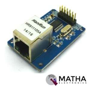
ENC28J60 ETHERNET MODULE
- ENC28J6 Ethernet chips, SOP28 package
- Operating voltage: 3.1V to 3.6V (3.3 V typical)
- Operating temperature: -40 degree to +85 degree Celsius
- IEEE 802.3 compatible Ethernet controller
- Buffer size: 8Kb
- Supports full and half-duplex mode
- SPI interface with a clock speeds up to 20MHz
- Programmable automatic rejection of erroneous packets
- Programmable automatic retransmit on a collision
- Programmable padding and CRC generation
- 25 MHz crystal oscillator
- Clock out the pin with a programmable presale
- Ethernet LAN module for Arduino/AVR/LPC/STM3
- 5V tolerant inputs
- SPI interface
- Led power indicator
- Dimension: 58*34*17mm
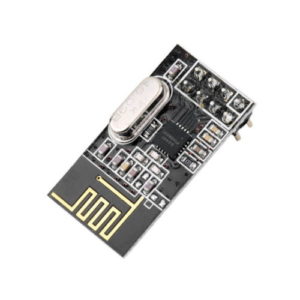
Mini SMD NRF24L01 2.4G Wireless Data Transmission Module
- Maximum operating speeds up to 2Mbps
- GFSK modulation efficiency, Anti-interference ability,
- Built-in hardware CRC error detection, Multipoint communication address control.
- Low-power 1.9 to 3.6V, only 1uA on Power-down mode
- Built-in 2.4Ghz antenna
- Built-in voltage regulator
- 125 Channels, Multi-point communication, and frequency hopping to meet the communication needs
- Wireless transceiver including Frequency generator, enhanced type, SchockBurstTM, mode controller, power amplifier, crystal amplifier, modulator, demodulator
- The output power channel selection and protocol settings can be set extremely low current consumption, through the SPI interface
- In the transmit mode, the transmit power is 6dBm, the current is 9.0mA, the accepted mode current is 12.3mA, the current consumption of the power-down mode and standby mode are lower
- Standard DIP Pitch Interface for embedded applications.NRF24L01 SPI interface: hardware SPI port, MCU I/O ports
- Internal FIFO compatible with a variety of microprocessor interface, micro-controller is convenient

PR34 2004 LCD Display Smart Controller W or Adapter for RAMPS1.4 Reprap 3D Printer
- RAMPS 1.4 2004 LCD Display intelligent controller.
- LED background light control circuit, a small function of the intelligent controller,
- With pin short time to decide on all LED turn or steering 30 seconds
- You can turn on the light time to do the long or short form of the adjustment TRIMM R4100K from 10 seconds to 2 minutes.
- Plug and play on the RAMPS, but need to modify the firmware to support.
- The product comes encoder parameter adjustment can be achieved, and the file selection print.
- With an SD card base on the back, put slicing file into the SD card and select the file on the LCD, then can be printing.
Reviews
There are no reviews yet.