
I am text block. Click edit button to change this text. Lorem ipsum dolor sit amet, consectetur adipiscing elit. Ut elit tellus, luctus nec ullamcorper mattis, pulvinar dapibus leo.
-14%Sold out


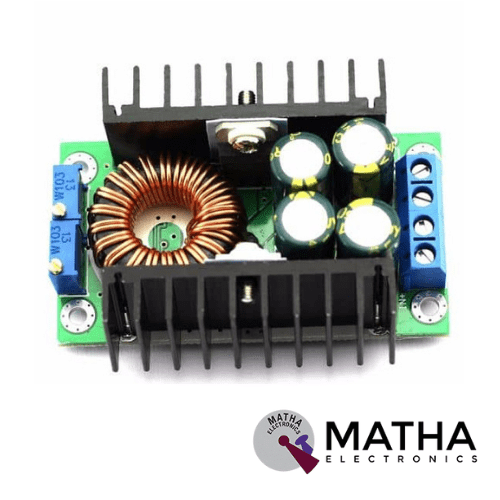
10A DC-DC Step-down Adjustable Constant Voltage Module
Original price was: ₹700.00.₹650.00Current price is: ₹650.00. inc. GST
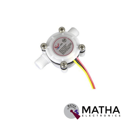
YF-S402 High Precision Flow Meter Water Flow Sensor
Original price was: ₹700.00.₹675.00Current price is: ₹675.00. inc. GST
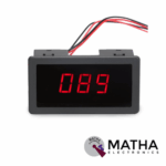
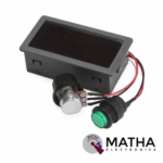
6V 12V 24V 8A PWM DC Motor Speed Controller CCM5D Digital Display LED Motor Controller Speed Regulator
Original price was: ₹700.00.₹600.00Current price is: ₹600.00. inc. GST
- Input Supply Voltage: 6V-30VDC
- Continuous Current (A): Rated current 5A (8A MAX, cannot be prolonged)
- Maximum Output Power: 240W
- LED display the duty ratio: 0-100%
- PWM Frequency: 16khz
- Duty Cycle adjustable: 0%-100%
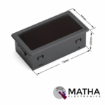
- Dimensions: 78*42*25mm
- The display range of 3-digit LED display is “000”-“100”.
- Adjustable speed range is 0%-100%
- Fine workmanship and good performance.
- Easy to use.
- Long service life.
- Suitable for the DC motor (or DC load) within 5A, Peak current 8A.
- Incorporate a push key. Push closed, and then push open
Out of stock
Description
This CCM5D DC Motor Speed Controller is used for controlling the direction of a DC motor using a Pulse-Width Modulated (PWM) DC voltage. It provides a DC voltage with a Duty Cycle fully adjustable from 0%-100%. The motor speed controller is Suitable for the DC motor (or DC load) within 5A, Peak current of 8A. And also used to drive all DC Brushed Motors that work between 6V and 30V DC. Moreover, this module has the function of a digital display whose digital tube displays the duty ratio input. The numerals are shown on a large 0.56-inch 3-digit LED that can be seen in the dark. “000-100” is the display range of a 3-digit LED display.
In the speed control of DC motors, pulse-width modulation (PWM) or duty-cycle variation techniques are often utilised. During a PWM period, the duty cycle is defined as the fraction of digital ‘high’ to digital ‘low,’ as well as the digital ‘high’ pulse-width. This is an excellent way to manage the amount of power given to a load without wasting any electricity. The motor can be positive or negative, and if the direction of operation and expectations don’t match, you can alter the direction by adjusting the line order.
Operating instruction:
- Before trying to wire the controller, make sure the power is off.
- Reversing positive and negative power will damage the controller.
- In order to change motor direction, interchange the positive and negative wires of the motor.
- Push the key, the controller closes; push it again, the controller opens.
- Please allow 1-5mm errors due to manual measurement.
Reviews (0)
Shipping & Delivery

Related products

40A DC MOTOR SPEED REGULATOR PWM CONTROLLER 2000W
- Speed controller model: 40A PWM DC motor speed regulator
- Operating voltage: 10V TO 50V
- Peak current: 40A
- Control power: 0.01-2000W
- Quiescent current: 0.025A
- PWM regulation: 5-100%
- PWM frequency: 12KHz
- Operating temperature: -20 degree to 40 degree Celsius
- Stability in working
- High efficiency
- potentiometer used for speed adjustability
- Dimension: 9*5.1mm
- Weight: 95gm

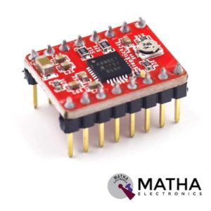
A4988 Stepper Motor
- Operating voltage supply: 8 V to 35 V
- Continuous current per phase: 1 Amp
- Maximum current per phase: 2 Amp
- Minimum logic voltage: 3V
- Maximum logic voltage: 5.5V
- Microstep resolutions: Full, 1/2, 1/4, 1/8, and 1/16
- Logic Voltage supply: 3.3 V to 5 V
- Compatible with 3V3 and 5V microcontrollers
- Our Board comes with 0.1 Ohm Sensor resistors
- Five different step resolutions: full-step, half-step, quarter-step, eighth-step, and sixteenth-step
- The Correct current decay mode (fast decay or slow decay) is selected by chopping the control
- Over-temperature thermal shutdown, under-voltage lockout, and crossover-current protection
- Short-to-ground and shorted-load protection
- 4-layer, 2 oz copper PCB for improved heat dissipation
- Exposed solderable ground pad below the driver IC on the bottom of the PCB
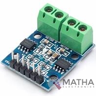
L9110 DC Stepper Motor Driver Board H-Bridge
- Low static work current
- Power supply voltage: DC2.5-12V
- Each channel has 800mA continuous current output
- Low saturation pressure drop
- TTL/CMOS output level compatible can be connected directly to the CPU
- Output built-in clamping diode, apply to the perceptual load
- Control and drive integrated into IC
- Have pin high-pressure protection function
- Working temperature: 0-80 °C
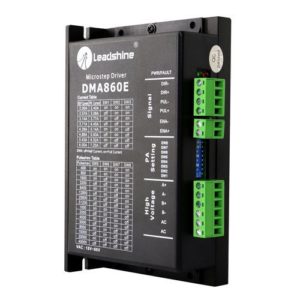
Leadshine DMA860E Stepper Motor Driver
- Model: DMA860E.
- Control Mode: Step & Direction.
- Max Input Frequency: 200 kHz.
- Input Voltage Range: 18 - 80 VAC / 24 - 110 VDC.
- Suggested Power Supply Voltage Range: 36-90 VDC /24-60 VAC.
- Number of DIP Switch Resolution Configurations: 16.
- 16 selectable micro-step resolutions of 400-51,200 via DIP switches.
- 8 selectable output current settings of 2.4 – 7.2A via DIP switches.
- Logic Current Range: 7-16mA (10mA typical).
- Logic Voltage Range: 4-5 VDC for pulse active high (default), or 0-0.5V for pulse active low.
- Pulse enabled at: Rising edge.
- Idle Current Percentage: 50 %.
- Number of Digital Inputs: 3.
- Step Width: 2,500 ns.
- Minimal Direction Setup Time: 5,000 ns.
- Isolation Resistance: 500M Ohm..
- Ambient Temperature: 0-50°C.
- Humidity: 40–95% RH.
- Operating Temperature: 0-70°C.
- Vibration: 5.9 m/s2 Max.
- Motor auto-identification and parameter auto-configuration for optimal torque from wide-range motors.
- Step & direction (PUL/DIR) and CW/CCW (via internal jumper set) control. Step & direction by default Multi-Stepping for smooth motor movement.
- Opto Isolation for input control signals.
- Soft-start with no “jump” when powered on.
- Protections for over-voltage and over-current.
- Dimension: 5.94 X 3.82 X 2.24 Inches.
- Weight: 1.13 lbs.
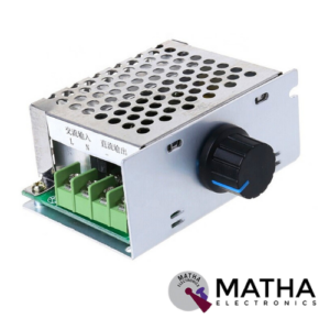
PWM DC Motor Speed Controller 20A
- Adjustable speed range: 0%-100%.
- Speed adjustment way: Potentiometer.
- Output voltage: Linear under load.
- Speed control type: Basins.
- Output voltage: Load Linear
- Type: Adjusting flow
- The motor running condition adjustment: Forward /Stop / Reverse
- Reverse polarity protection: Yes.
- Suitable Motor: DC brush motors.


TB6612FNG Dual Motor Driver Module 1A for Arduino/Other Microcontroller
- Driver Model: TB6612FNG
- Operating voltage: 2.7 V to 5.5 V
- Limited Maximum Voltage: 15V max
- Output current: 1.2A
- Maximum Current: 3.2A (peak)
- Number of Channels: 1
- Standby control to save power
- CW/CCW/short break/stop motor control modes
- Built-in thermal shutdown circuit and a low voltage detecting circuit
- All pins of the TB6612FNG broken out to 0.1 spaced pins
- Filtering capacitors on both supply lines
- Dimensions: 30 x 20 x 10mm
- Weight: 22 gm
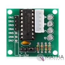
ULN2003 Driver
- Contains 7 high-voltage and high current Darlington pairs
- Each pair is rated for 50V and 500mA
- Input pins can be triggered by +5V
- All seven Output pins can be connected to gather to drive loads up to (7×500mA) ~3.5A.
- Can be directly controlled by logic devices like Digital Gates PIC etc
- Available in 16-pin DIP, TSSOP, SOIC packages
- Dimensions: 32 x 18 x 11mm (LxWxH)
- Weight: 3 gm
Reviews
There are no reviews yet.