
I am text block. Click edit button to change this text. Lorem ipsum dolor sit amet, consectetur adipiscing elit. Ut elit tellus, luctus nec ullamcorper mattis, pulvinar dapibus leo.
-17%

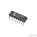
74LS251 Data Selector or Multiplexer IC With 3-State Output
Original price was: ₹35.00.₹25.00Current price is: ₹25.00. inc. GST
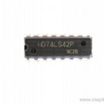
74LS42 BCD to Decimal Decoder IC
₹45.00 inc. GST
74LS154 4 Line to 16 Line Decoder Demultiplexer IC
Original price was: ₹120.00.₹100.00Current price is: ₹100.00. inc. GST
- 4 Line to 16 Line Decoder/Demultiplexer
- High-level input voltage: 2V
- Low-level input voltage: 0.8V
- High-level output current: -0.4mA
- Low-level output current: 8mA
- Input clamp voltage: -1.5V
- Propagation delay time max: 35ns
- Typical power dissipation: 45mW
- Supply voltage range: 4.75 to 5.25V
- Package: DIP-24
Description
The 74HC154 designed as a 4-to-16 line decoder/demultiplexer. It converts sixteen mutually exclusive outputs (Y0 to Y15) from four binary weighted address inputs (A0 to A3). TTL circuitry is used in each of these 4-to-16-line decoders. When both the strobe inputs, G1 and G2, are LOW, this circuit decodes four binary-coded inputs into one of sixteen mutually exclusive outputs. The demultiplexing function is carried out by addressing the output line with the four input lines.
As a result, data from one of the strobe inputs is passed to the other strobe input, which is set to LOW. All outputs are HIGH when either strobe input is HIGH. These demultiplexers are ideal for building memory decoders with high performance. To minimise transmission-line impacts and simplify system design, all inputs are buffered and input clamping diodes are provided. Clamp diodes are used as inputs. As a result, these current limiting resistors permits to be used to interface inputs to voltages greater than VCC.
A demultiplexer designed as a combinational logic circuit that switches a single common input line to one of numerous distinct output lines. The data distributor, often known as a Demultiplexer or “Demux,” is a device that distributes data. In a nutshell, this is the polar opposite of the Multiplexer from the last tutorial. The demultiplexer takes a single input data line and switches it one at a time to any of a number of distinct output lines. A serial data signal is fed into the demultiplexer, which converts it to parallel data on the output lines.
Reviews (0)
Shipping & Delivery

Related products


650NM Laser Diode
- Wavelength: 650nm
- Output optical power: 5mW
- Operating voltage: 5V
- Operating current: ~30mA
- Input current: 30mA
- Housing material: Copper
- Power lead length: 120mm.
- Transmit power: 58mW
- Spot: size 10mm to 15mm at 15meters
- Life span more than 2000 hours
- Driver circuit: APC circuit
- Small size
- Cost-effective
- Breadboard friendly
- Operating temperature -10°C to 40°C
- Dimension: :15mm x 6mm
- Weight: 10 grams

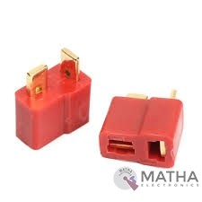
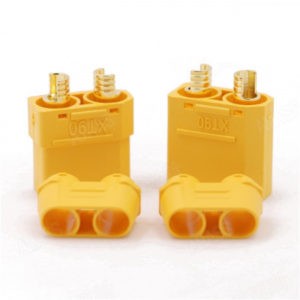
Dean Connector
- Male plug size: About 13* 7* 19mm
- Female plug size: About 13* 7* 15mm
- Current Rating: 30Amps
- Colour: Red and golden
- Material: Plastic and metal
- Provides a secure connection for battery and motor connections
- Eliminates the possibility of wrong polarity connections
- Used in RC hobby, car, boat, plane, helicopter, LIPO battery, etc.
- Dimension: 9x0.7x2cm
- Weight:20gm

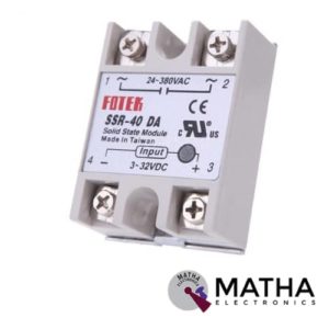

Solid State Relay SSR-40DD 40A 3-32V DC to 5-60V DC SSR 40DD Relay Solid State
- Model: SSR-40 DD.
- Control mode: DC-DC
- Input voltage: 3-32V DC.
- Output voltage: 5-60V DC.
- Output current: 40A.
- On voltage: ≤1v.
- One-off time: ≤10ms.
- Off leakage current: ≤2ma.
- Loading current: 40A
- Control current: 3-25mA DC
- Material: plastic + metal.
- Environment temperature: -30 to +75
- Long service life and high reliability.
- Reduced electromagnetic interference.
- Highly reliable, compact size designed to offer users maximum simplicity.
- Weight: 0. 106Kg.
Reviews
There are no reviews yet.