
I am text block. Click edit button to change this text. Lorem ipsum dolor sit amet, consectetur adipiscing elit. Ut elit tellus, luctus nec ullamcorper mattis, pulvinar dapibus leo.
-13%


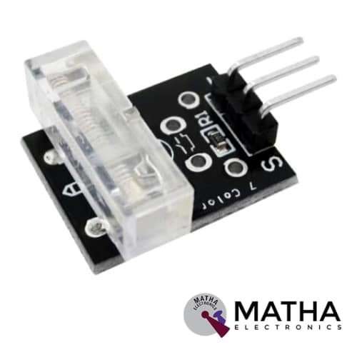
TAP Sensor Module
Original price was: ₹150.00.₹140.00Current price is: ₹140.00. inc. GST
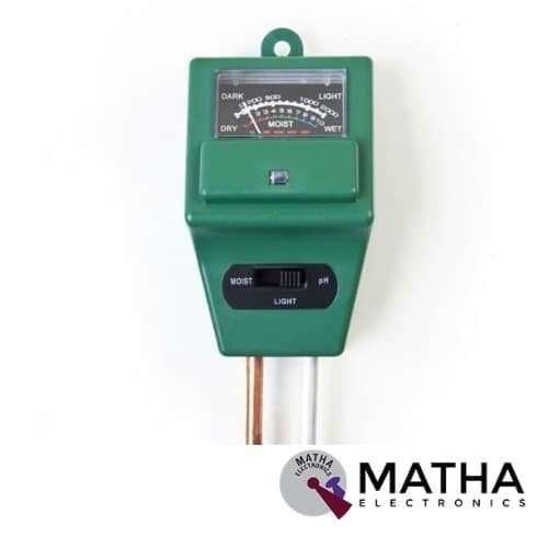
PH Tester Soil Water Moisture Light Test Meter Sensor
Original price was: ₹650.00.₹600.00Current price is: ₹600.00. inc. GST
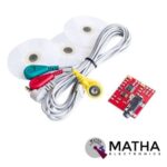
EMG Sensor / Muscle Sensor Module For Arduino
Original price was: ₹3,000.00.₹2,600.00Current price is: ₹2,600.00. inc. GST
- Power Supply: Normally ±9V dual power supply, the minimum voltage is ±3.5V
- The diameter of the Electrode Pad: 52 mm
- Cable Length: 2 feet
- Improved adjustable gain (more rugged)
- 5mm connector
- On-board port for new cables Connects to the board straight out of the box
- Supported with Arduino, Breadboard mountable
- Weight: 30gm.
Description
Electromyography (EMG) sensor is defined as muscle response or electrical activity measuring device in response to a nerve’s stimulation of the muscle. The test was employed to detect neuromuscular abnormalities. During the test, one or more small electrode needles are inserted through the skin into the muscle. The electrical activity achieved by the electrodes is further displayed on an oscilloscope (a monitor that displays electrical activity within the sort of waves). An audio-amplifier is employed therefore the activity is often heard. The electrical activity of muscle is measured during rest, slight contraction, and forceful contraction. Muscle tissue doesn’t normally produce electrical signals during rest. When an electrode is inserted, a quick period of activity is often seen on the oscilloscope, but then, no signal should be present.
After an electrode is inserted, you should contact the muscle, for instance, lifting or bending your leg. The nerve impulse on the oscilloscope provides information about the power of the muscle to reply when the nerves are stimulated. When more muscles contract forcefully, more and more muscle fibres are activated, thereby producing action potentials.
Using a cable and electrodes muscle sensor measures filters, rectify, and amplifies the electrical activity of a muscle and produces an analogue output signal. A microcontroller, enabling novel, muscle-controlled interfaces for your projects, can easily read these signals. It outputs Depending on the amount of activity in the selected muscle, it outputs signal 0-Vs Volts, where Vs signifies the voltage of the power source. It operates at a minimum Power supply voltage of +-3.5V. The impulse on the oscilloscope provides information about the power of the muscle to reply when the nerves stimulate.
Reviews (0)
Shipping & Delivery

Related products


10D OF 9-AXIS GY-87
- Power supply: DC 3.3V TO 5V
- 3 Axis Gyro+ Acceleration+ Magnetic field
- Air pressure module
- Inbuilt ultra-low noise linear LDO voltage regulator
- Inbuilt onboard filters. which reduce noise from motor and another high current
- Communication: I2C protocol
- Power LED
- Designed for 5V logic
- Can easily select two I2C addresses for MPU6050 by soldered jumper
- Dimension: 2.2*1.7cm
- Size: 6gm
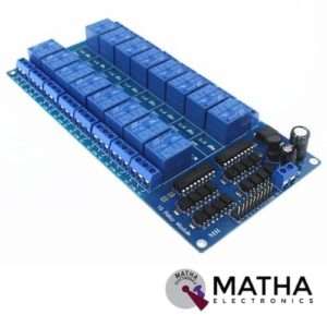
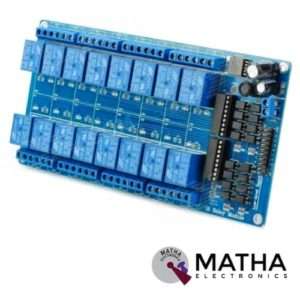
16 CHANNEL 5V RELAY
- 16 channel 5V relay board
- Operating voltage: 5V
- Supply current: 500mA
- Relay contact current capacity of 10A @250 V AC/10A@ 30V AC
- Optocoupler protection
- Low state voltage: 0V to 0.5V (relay is ON)
- High state voltage: 3.7V to 5V(relay is OFF)
- Single-chip design with reliable performance
- Strong anti-interferences
- Strong anti-jamming ability and stable performance
- The on-board power supply module doesn’t need any external power
- Common terminal(com) in each rely is user friendly and can be accessed by different signal
- Dimension: 180*90*20mm
- Weight: 100gm
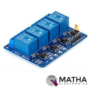

4 CHANNEL 12V RELAY
- 4-Channel relay interface board
- Relay input voltage: 12V DC
- Relay output: 5A/250V AC
- Signal input:5V DC from the microcontroller
- High current relay of 10A @250 V AC/10A@ 30V DC
- For quick and easy connection high-quality screw terminals provided
- Can control both AC & DC appliances such as DC motors, solenoid valves, lamps, etc.
- LED status indicates relay ON/OFF state.
- Power battery terminal for relay output and aux power connection
- Standard interface that can be controlled by a microcontroller (Arduino, 8051, PIC, AVR, DSP, ARM)
- Relay can directly control all equipment’s and loads
- For easy accessibility input signal pin connected to burg sticks
- Dimension: 165*65*1mm
- Weight: 7gm

4*4 MATRIX KEYPAD
The maximum voltage across each button: 24v
- The maximum current across each button: 3mA
- Easy communication with any microcontroller
- Ultra-thin design
- Adhesive backing provides easy integration
- High price-performance ratio
- Allows microcontroller to scan 8 output pins to check which 16 button
- Long life
- Maximum operating temperature: 0 degrees to 50 degrees Celsius
- Dimension: 70*77*1mm
- Weight: 7.5gm
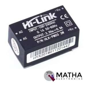

AC-DC Power Module HLK-PM03 230V to 3.3V /3W
- Meet UL, CE requirements
- Rated input voltage: AC 100V -230V
- Input voltage range: 90V -264V AC
- Maximum input current: <0.2A
- Input current surge: <10A
- Maximum input voltage: <270V AC
- Input Low Voltage Efficiency Vin=110V AC,Output full-load≥ 69%
- Input High Voltage Efficiency Vin=220V AC,output full-load≥ 70 %
- Long-term reliability
- Voltage Regulation: ±0.2%
- Load Regulation: ±0.5%
- Ultra-thin and small module
- High efficiency, high power density
- Low ripple and low noise
- Output overload and short circuit protection
- Working temperature: – 20 degrees to +60 degrees Celsius
- Storage temperature: -40 degrees to 80 degrees Celsius
- Relative humidity: 5-95%
- Cooling way: Natural cooling
- Atmospheric pressure: 80-106Kpa
- Weight: 21g
- Size: 38x23x18mm


I2C MODULE WITH 16*2 CHARACTER LCD
- Supply voltage: 5V
- Display mode: STN
- Display format: 16*2
- Input data: 4 bit or 8 bit (for LCD)
- I2C address: 0x20~0x27 (original address is 0x20,we can change it ourselves)
- Compatible with multiple communication logic levels: 2.8~5VDC
- Compatible for 16*2 LCD
- Serial I2C control of LCD display using PCF8574
- Allow data display via only 2 wires.
- Backlight and contrast adjustment by the potentiometer
- Supports 7 ASCII fonts, 5 graphic functions
- Supports 128 level backlight lightness adjustment.
- Support 64 level screen contrast adjustment
- Supports device address modification
- Dimension: 10*4*5cm
- Size: 150gm


IRF520 MOSFET DRIVER MODULE SENSOR
- Operating Voltage: 3.3v & 5v
- Digital level port
- Output load voltage: 0-24v
- Output load current: <5A
- The heat sink is added for currently more than 1A
- Compatible with Arduino, MCU, ARM, Raspberry pi
- PWM dimming LED used to step-less dimming, variable-speed motor
- Output PWM can be adjusted by the original IFR520 MOS
- Arduino can drive up to 24V, such as led lights, dc motors, miniature pumps, solenoid valves etc.
- Dimension:34*30*18mm
- Size: 10gm
Reviews
There are no reviews yet.