
I am text block. Click edit button to change this text. Lorem ipsum dolor sit amet, consectetur adipiscing elit. Ut elit tellus, luctus nec ullamcorper mattis, pulvinar dapibus leo.
-13%


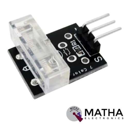
TAP Sensor Module
Original price was: ₹150.00.₹140.00Current price is: ₹140.00. inc. GST
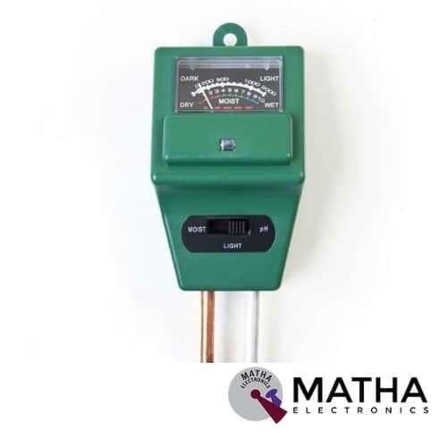
PH Tester Soil Water Moisture Light Test Meter Sensor
Original price was: ₹650.00.₹600.00Current price is: ₹600.00. inc. GST
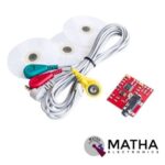
EMG Sensor / Muscle Sensor Module For Arduino
Original price was: ₹3,000.00.₹2,600.00Current price is: ₹2,600.00. inc. GST
- Power Supply: Normally ±9V dual power supply, the minimum voltage is ±3.5V
- The diameter of the Electrode Pad: 52 mm
- Cable Length: 2 feet
- Improved adjustable gain (more rugged)
- 5mm connector
- On-board port for new cables Connects to the board straight out of the box
- Supported with Arduino, Breadboard mountable
- Weight: 30gm.
Description
Electromyography (EMG) sensor is defined as muscle response or electrical activity measuring device in response to a nerve’s stimulation of the muscle. The test was employed to detect neuromuscular abnormalities. During the test, one or more small electrode needles are inserted through the skin into the muscle. The electrical activity achieved by the electrodes is further displayed on an oscilloscope (a monitor that displays electrical activity within the sort of waves). An audio-amplifier is employed therefore the activity is often heard. The electrical activity of muscle is measured during rest, slight contraction, and forceful contraction. Muscle tissue doesn’t normally produce electrical signals during rest. When an electrode is inserted, a quick period of activity is often seen on the oscilloscope, but then, no signal should be present.
After an electrode is inserted, you should contact the muscle, for instance, lifting or bending your leg. The nerve impulse on the oscilloscope provides information about the power of the muscle to reply when the nerves are stimulated. When more muscles contract forcefully, more and more muscle fibres are activated, thereby producing action potentials.
Using a cable and electrodes muscle sensor measures filters, rectify, and amplifies the electrical activity of a muscle and produces an analogue output signal. A microcontroller, enabling novel, muscle-controlled interfaces for your projects, can easily read these signals. It outputs Depending on the amount of activity in the selected muscle, it outputs signal 0-Vs Volts, where Vs signifies the voltage of the power source. It operates at a minimum Power supply voltage of +-3.5V. The impulse on the oscilloscope provides information about the power of the muscle to reply when the nerves stimulate.
Reviews (0)
Shipping & Delivery

Related products
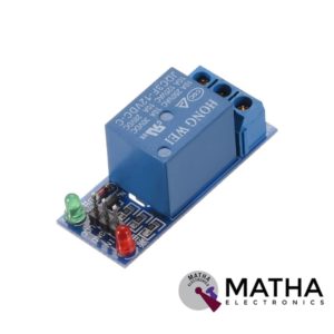
1 CHANNEL 12V RELAY
- 1-Channel relay interface board
- Operating voltage: 12V DC
- Provide high current relay of 15A
- For quick and easy connection high-quality screw terminals provided
- Can control both AC & DC appliances
- LED status indicates relay ON/OFF state.
- High current relay of 10A @250 V AC/10A@ 30V DC
- Standard interface that can be controlled by a microcontroller (Arduino, 8051, PIC, AVR, DSP, ARM)
- For easy accessibility input signal pin connected to burg sticks
- Dimension: 43*17*17mm
- Weight: 150gm

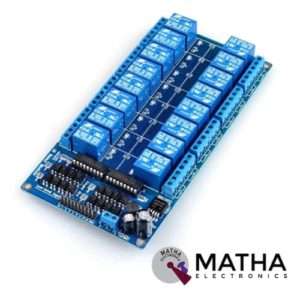
16 CHANNEL 12V RELAY
- 16 channel 12V relay board
- Operating voltage: 12V
- Supply current: 0.2 A
- Relay contact current capacity of 10A @250 V AC/10A@ 30V AC
- Optocoupler protection
- LED status indicates relay ON/OFF state.
- The 10-16 road can be any full-on/off or any road
- Common terminal(com) in each rely is user friendly and can be accessed by different signal
- Normally closed or normally open with each port
- Strong anti-jamming ability and stable performance
- The on-board power supply module doesn’t need any external power
- Dimension: 180*90*20mm
- Weight: 100gm


2 CHANNEL 5V RELAY
- High current relay
- Two LED S to indicate relays ON/OFF status
- Low-level trigger expansion board
- Opto isolation circuitry
- Works with logic level signal 3.3V or 5V devices
- Can be used as normally open (NO) or normally closed (NC)
- Back EMF protection
- Ensures diode current protection
- AC control voltage: 250v @mx10A
- DC control voltage: 30V @max 10A
- Easy installation and fixing
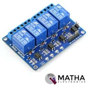

4 CHANNEL 5V RELAY
- 4-Channel relay interface board
- Operating voltage range: 3.3V to5V
- Maximum current: 10A
- Supply current: 20 mA
- High current relay of 10A @250 V AC/10A@ 30V DC
- Control signal: TTL level
- For quick and easy connection high-quality screw terminals provided
- Pull-down circuit to avoid malfunction
- Power supply indicator
- Can control both AC & DC appliances such as DC motors, solenoid valves, lamps, etc.
- LED status indicates relay ON/OFF state.
- Standard interface that can be controlled by a microcontroller (Arduino, 8051, PIC, AVR, DSP, ARM)
- For easy accessibility input signal pin connected to burg sticks
- Operating temperature: -40 to 85 degrees Celsius
- Dimension: 76*56*17mm
- Weight: 7gm
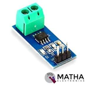

CURRENT SENSOR ACS712 30AMPS
- Current sensor chip: ACS712ELC-30A
- Supply voltage: 4.5V to 5.5V DC
- Current range: -30A to 30A
- Sensitivity: 66 millivolt/ampere
- Low noise analogue signal path
- Output rise time: 5 micro sec
- Extremely stable output offset voltage
- Zero magnetic hysteresis
- Factory trimmed for accuracy
- Easy to interface with a microcontroller, since it outputs an analogue voltage
- Onboard power indicator
- Dimension: 7*5*5cm
- Weight: 400gm
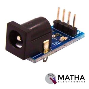


IRF520 MOSFET DRIVER MODULE SENSOR
- Operating Voltage: 3.3v & 5v
- Digital level port
- Output load voltage: 0-24v
- Output load current: <5A
- The heat sink is added for currently more than 1A
- Compatible with Arduino, MCU, ARM, Raspberry pi
- PWM dimming LED used to step-less dimming, variable-speed motor
- Output PWM can be adjusted by the original IFR520 MOS
- Arduino can drive up to 24V, such as led lights, dc motors, miniature pumps, solenoid valves etc.
- Dimension:34*30*18mm
- Size: 10gm

Reviews
There are no reviews yet.