
I am text block. Click edit button to change this text. Lorem ipsum dolor sit amet, consectetur adipiscing elit. Ut elit tellus, luctus nec ullamcorper mattis, pulvinar dapibus leo.

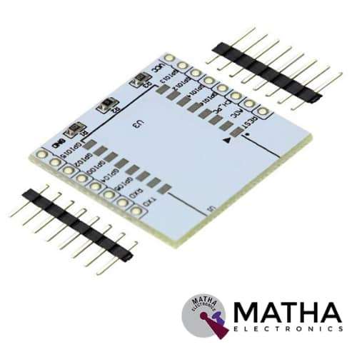
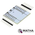
ESP8266 Serial Wifi module Adapter Plate
₹150.00 inc. GST
- PCB Colour: White
- PCB Thickness: 1.6mm
- It features a reserved land pattern for the 3.3V regulator
- It has Pinouts on the top layer in black colour.
- Compatible with Latest ESP-12F ESP8266 Wifi Module
- It includes a 10K pull-up resistor populated on PCB.
- Ease to an interface.
- Ease to use.
Description
This ESP8266 Serial Wireless WIFI Module Adapter Plate is designed explicitly for ESP-07, ESP-08, ESP-12E ESP8266 SMD ESP8266 Module. These SMD ESP8266 modules come with an unfriendly pin pitch. You may use your favourite ESP8266 SMD modules on breadboards or perforated boards by soldering ESP-07, ESP-08, or ESP-12E modules to this adaptor PCB. The ESP8266 serial wifi adapter plates are used to connect the Wi-Fi module. These modules may be used in a broad range of DIY projects. It also has short-circuit protection, which guarantees that communication between applications is reliable. It is the most frequent and secure method of connecting and detaching different wifi modules. The ESP8266 is a self-contained Serial Wifi Wireless Transceiver Module with a TCP/IP protocol stack built in. Any microcontroller may connect to your WiFi network using it. This Module can either run an application or offload all Wi-Fi networking tasks to a different CPU.
ESP8266 adapter plate works perfectly with the ESP07, ESP08, and ESP12. This adaptor plate is offered since soldering the ESP modules is not always straightforward. The WiFi module is readily attached to the PCB, where it is coupled to headers that clearly identify connecting locations. Meanwhile, a land pattern for a 3.3V regulator can be found on the bottom layer. We must desolder jumper resistor R1 in order to use this 3.3V regulator. To the 9V power input, the VCC pin becomes 4.5V. Hence It works perfectly ESP-07, ESP-08, and ESP-12.
Reviews (0)
Shipping & Delivery

Related products


ESP8266 WIFI Industrial stable version A full test board cloud function test Black board T5
- Support 802.11b / n / g wireless standard
- Independent development MCU platform
- High cost performance
- Support UART / GPIO data communication interface
- Support STA / AP / STA + AP coexistence mode of operation
- Support SmartLink intelligent networking (APP)
- Support wireless upgrade firmware
- Support WPS network configuration
- Built-in onboard antenna &Temperature and humidity sensor
- RGB three-color light adjustable
- Provide rich AT command set configuration
- Free AiCloud cloud service for debugging
- 3 AA batteries / 5V adapter power supply
- Size: 61.6mm x 56.2mm;

ESP8266-12E 10A 220V NETWORK RELAY WIFI MODULE INPUT DC 7V-30V
- Input voltage: DC 7V-30V
- Relay voltage: 220V
- Relay current: 10A
- ISM: 2.4GHz
- PA: +25dBm
- Input over-voltage protection
- Input overcurrent protection
- ESP8266 WIFI module with 4 layered board design
- LED indicator for input status and output status
- 220V 10A relay, normally opened, and one normally closed
- Optocoupler isolation input, TVS input protection
- Access server control via HTTP protocol by TCP client mode, high current terminals
- Dimension: 65*40*18mm


Mini ESP-M2 ESP8285 Serial Wireless WiFi Transmission Module SerialNET MODE Fully Compatible With ESP8266
ESP8285 M2 WiFi IoT Module :
- SOC characteristics.
- Built-in Tensilica L106 ultra-low power 32-bit CPU, main frequency supports 80MHz and160MHz and RTOS.
- Built-in TCP/IP protocol.
- Built-in one-channel 10-bit high precision ADC.
- Outboard interface: HSPI, UART, I2C, I2S, IR Remote Control, PWM, GPIO.
- The deep sleep current is 10uA, the cut-off current is smaller than 5uA.
- Wake, connect and transmit data package within 2ms.
- The consumer power is smaller 1.0Mw (DTIM3) when at standby status.
- Built-in 1M byte for SPI Flash.
- Ultra-small size.
- Support serial to WiFi.
- Wireless transparent transmission.
- Long-distance transmission with ultra-low power.
- Support outboard antenna.
- Bearing high temperature to 125 °C, compared to the 85°C for ESP8266.
- Support 802.11 b/g/n/e/I.
- Support Station, Soft AP, Soft AP+STA mode.
- Support WiFi Direct (P2P).
- Support CCMP (CBC-MAC, computation mode), TKIP (MIC, RC4), WAPI (SMS4), WEP (RC4), CRC etc., for hardware acceleration.
- P2P finding, P2P GO mode/ GC mode and P2P power management.
- WPA/PA2PSK and WPS.
- 11securitycertification: pre-certification and TSN.
- Support 802.11n (2.4GHz).
- 1h/RFC1042 frame encapsulation.
- Support seamless roaming.
- Support AT remote update and cloud update (OTA).
- Support Smart Config function (including Android and Ios device
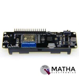
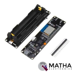
WeMos D1 ESP Wroom 02 Board ESP8266 Mini WiFi Nodemcu Module 18650 Battery
- One AD inputs.
- Micro USB inputs.
- One programmable LED (D0).
- AUTO PROGRAM circuit.
- ESP8266 (ESP-WROOM-02 With TELEC) is equivalent to the NodeMCU.
- Analog Input (AD): Built-in dividing resistor (AD = 220K ADC 100K = GND).
- There is a SOLDER terminal for SLEEP MODE.
- Compatible With Arduino andNodeMCU.
- Operation and charging are possible at the same time.
- 18650 charging circuit including the 5V boosting circuit with TP5410.
- Overcharge protection, over-discharge protection built-in.
- LED: Red = Charging, Green = Full charging.
- 3000 mA 18650 It is possible to operate for more than 17 hours on a battery.
- Integrated 18650 battery charging and discharging system.
- One switch controls whether the 18650 battery is on power or not.
- OLEDs SDA and SCL can connect to the D1 pin and the D2 pin respectively.
- The five buttons can be controlled by FLATH, RSET, D5, D6, and D7 respectively.
- The 5 Digital pins can configure the write/read/interrupt/PWM/I2C/one-wire supported separately.
- Operation and NodeMCU consistent, adding a programmable LED, you can use GPIO16 to control; display 8266 running status and other functions. Integrated OLED and five buttons, more convenient for development.
- The design concept originates from the open-source project NodeMCU; the development board integrates 18650 charging and discharging systems with charging and discharging protection. At the same time, an OLED and five directional buttons are integrated to facilitate the development.

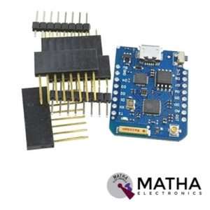
Wemos D1 Mini ESP8266 NodeMCU WIFI board for Arduino
- Microcontroller: ESP-8266EX
- Operating Voltage: 3.3 V
- Digital I/O Pins: 11
- Analog Input Pins 1(Max input: 3.2V)
- Clock Speed: 80MHz/160MHz
- Flash: 4M bytes
- Length: 34.2mm
- Width: 25.6mm
- Use BRT (Bias Resistor Transistor)
- Easier into flash mode.
- 30% increase in radiating area
- Good stability.
- 11 digital input/output pins, all pins have interrupt/PWM/I2C/one-wire supported(except for D0)
- 1 analog input(3.2V max input)
- Micro USB connection
- Compatible with Arduino
- Compatible with Node MCU
- Support OTA wireless uploading
- 11 x I/O pins,1 x ADC pin
Reviews
There are no reviews yet.