
I am text block. Click edit button to change this text. Lorem ipsum dolor sit amet, consectetur adipiscing elit. Ut elit tellus, luctus nec ullamcorper mattis, pulvinar dapibus leo.

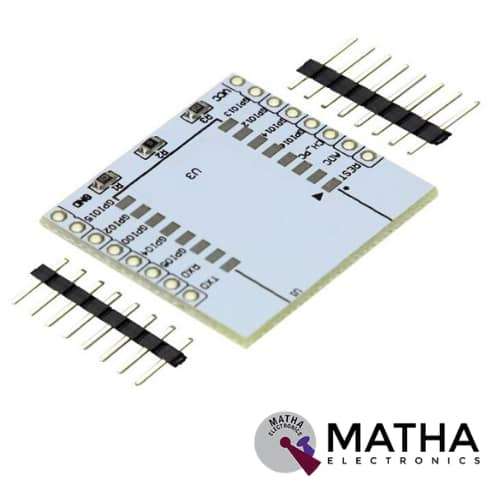
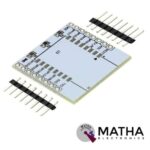
ESP8266 Serial Wifi module Adapter Plate
₹150.00 inc. GST
- PCB Colour: White
- PCB Thickness: 1.6mm
- It features a reserved land pattern for the 3.3V regulator
- It has Pinouts on the top layer in black colour.
- Compatible with Latest ESP-12F ESP8266 Wifi Module
- It includes a 10K pull-up resistor populated on PCB.
- Ease to an interface.
- Ease to use.
Description
This ESP8266 Serial Wireless WIFI Module Adapter Plate is designed explicitly for ESP-07, ESP-08, ESP-12E ESP8266 SMD ESP8266 Module. These SMD ESP8266 modules come with an unfriendly pin pitch. You may use your favourite ESP8266 SMD modules on breadboards or perforated boards by soldering ESP-07, ESP-08, or ESP-12E modules to this adaptor PCB. The ESP8266 serial wifi adapter plates are used to connect the Wi-Fi module. These modules may be used in a broad range of DIY projects. It also has short-circuit protection, which guarantees that communication between applications is reliable. It is the most frequent and secure method of connecting and detaching different wifi modules. The ESP8266 is a self-contained Serial Wifi Wireless Transceiver Module with a TCP/IP protocol stack built in. Any microcontroller may connect to your WiFi network using it. This Module can either run an application or offload all Wi-Fi networking tasks to a different CPU.
ESP8266 adapter plate works perfectly with the ESP07, ESP08, and ESP12. This adaptor plate is offered since soldering the ESP modules is not always straightforward. The WiFi module is readily attached to the PCB, where it is coupled to headers that clearly identify connecting locations. Meanwhile, a land pattern for a 3.3V regulator can be found on the bottom layer. We must desolder jumper resistor R1 in order to use this 3.3V regulator. To the 9V power input, the VCC pin becomes 4.5V. Hence It works perfectly ESP-07, ESP-08, and ESP-12.
Reviews (0)
Shipping & Delivery

Related products

ANTENNA WIFI
Antenna Specifications:
- Color: Black
- Radiation: Omni-directional
- Gain:8dBi
- Frequency Range(MHz): 2400-2500, 5150-5850MHz
- Connector Type: RP-SMA Male (Hole)
- Angle Adjustable: 90° 135° 180°
- Dimension: 16cm/ 6.3”(Unbend) / 13.5cm/ 5.31”(Bend)
- Wight: 13.5g / 0.48 oz per antenna
- Color: Black & Gold
- Length: 15cm / 5.9''
- Wight:4.4g / 0.17 oz per pigtail cable
- Connector Type: U.FL/ IPEX to RP-SMA Female
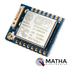
ESP8266 ESP – 07
- Smallest 802.11b/g/n Wi-Fi SOC module
- Low power 32-bit CPU, can also serve as the application processor
- Up to 160MHz clock speed
- Built-in 10 bit high precision ADC
- Supports UART/GPIO/IIC/PWM/ADC
- SMD-16 package for easy welding
- Integrated Wi-Fi MAC/BB/RF/PA/LNA
- Deep sleep current as low as 20uA
- Embedded LWIP protocol stack
- Supports STA/AP/STA + AP operation mode
- Support Smart Config/AirKiss technology
- UART baudrate up to 4Mbps
- General AT commands can be used quickly
- Supports remote firmware upgrade (FOTA)
- WIFI Direct (P2P),SOFT-AP
- Built-in TCP/IP
- The AT command is perfect, efficient, concise
- Support three modes: AP, STA and AP+STA coexistence mode
- Onboard Chip Antenna
- +19.5dBm output power in 802.11b mode
- Power down leakage current of <10uA
- SDIO 1.1/2.0, SPI, UART
- STBC, 1×1 MIMO, 2×1 MIMO
- A-MPDU & A-MSDU aggregation & 0.4ms guard interval
- Wake up and transmit packets in < 2ms
- Standby power consumption of < 1.0mW (DTIM3)
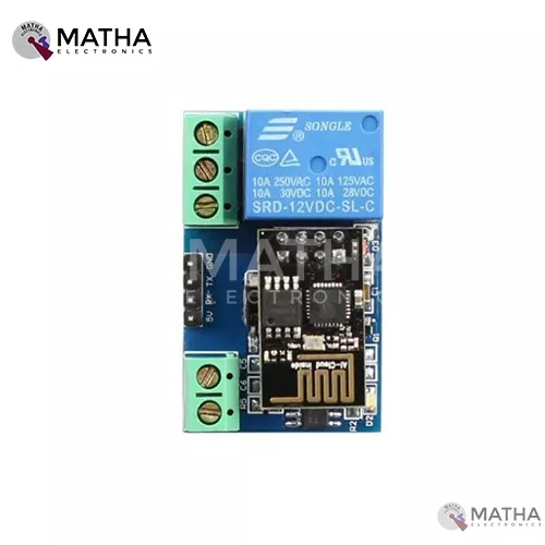
ESP8266- 01 5V WIFI RELAY MODULE TOI APP CONTROLLED FOR SMART HOME AUTOMATION
- Onboad module: ESP2866 WIFI module
- Onboard relay: 5v.10a/250v ac, 10a/30v dc
- Can connect 5 clients at the same time on AP mode
- The module has two work modes: Cell phone, carry on Wi-Fi module and Cell phone and Wi-Fi module carry on the same router
- Used in mobile phone, Wi-Fi module equipped with one router and control relay by APP
- Maximum transmission distance of 400 m when cell phone carry on wifi module directly, in the open environment
- Transmission distance depends on routers signal intensity when wifi and cell phone is carrying on the same router
- IN+, IN_: 5V power input
- TX, RX, and GND: serial port debug pins
- Baud rate: 115200
- Provide diode effusion protection
- Short response time
- Dimension: 45*28mm
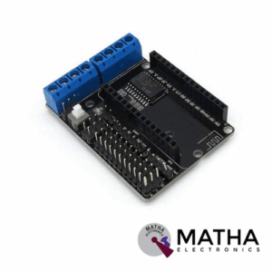

L293D Motor Driver Board for ESP8266 WiFi NodeMcu Lua ESP12E
- Motor power supply Range: 4.5V ~ 36V
- Control power Range: 4.5V ~ 9V (10VMAX)
- Logic Operating current: ≤60mA
- Drive part of the work current Io: ≤1.2A
- Maximum power dissipation: 4W
- Drive Type: Dual high-power H-bridge driver
- Working temperature: -25 ℃ ~ + 125 ℃
- ESP12 DEV KIT development board expansion module
- Lead ESP12 DEV KIT all the features of pins: SPI, UART, GPIO, AI, and 3.3V power connector
- Extend two-way motor-driven, two-way direct-drive motor
- on board power switch
- Motor power, control power separation
- Dimension: 60 x 45 x 13mm
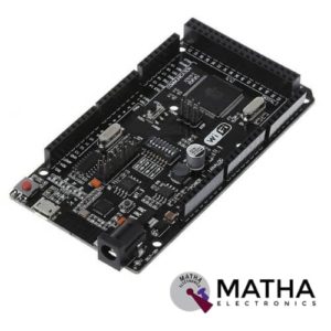
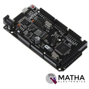
Mega R3 +WiFi ATmega2560+ESP8266 Module CH340G Compatible For Arduino Mega
- Microcontroller:ATmega2560
- IC Wi-Fi : ESP8266
- USB-TTL converter: CH340G
- Power Out: 5V-800mA
- Power Input USB: 5V (500mA max.)
- Power Input VIN/DC Jack: 9-24V
- Power Consumption: 5V 800mA
- Logic Level: 5V
- Wi-Fi 802.11 b/g/n 2.4 GHz
- USB: Micro USB
- Clock Frequency: 16MHz
- Operating Supply Voltage: 5V
- Digital I/O: 54
- Analog I/O: 16
- Memory Size: 256kb
- Data RAM Type/Size: 8Kb
- Data ROM Type/Size: 4Kb
- Interface Type: SerialOTA
- Operating temperature:−40С°/+125С°
- Build in external antenna
- Dimensions:53.361×101.86mm

NRF24L01 Long Range
- Voltage: 3-3.6V (recommended 3.3V) V.
- Maximum output power: +20dBm.
- Power-down mode current: 4.2uA.
- Operating Range: 1Km.
- Transmission mode current(peak): 115mA
- Receiver Mode Current(peak): 45mA
- Power-down mode current: 4.2uA
- Sensitivity 2Mbps mode in received: -92dBm
- It uses 2.4GHz global open ISM band, with license free.
- SPI interface facilitates the communication with MCU I/O port.
- Support six-channel data reception.
- 2Mbit/s speed makes high-quality VoIP possible
- Multi-frequency points: 125 frequency points meet the needs of multi-point communications and frequency hopping.
- Supports 126 RF channels
- Onboard antenna for optimum performance
- Standard DIP type pinout for easy Interface through jumper wires or breadboard
- Small size: 16.5mm*45.5mm.
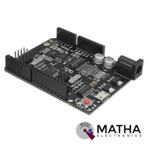

UNO R3 +WiFi ATmega328P+ESP8266 Module CH340G Compatible For Arduino Uno
- Microcontroller: ATmega328IC
- Wi-Fi: ESP8266
- USB-TTL converter: CH340G
- Power Output: 5V-800mA
- Power input USB: 5V (500mA max.)
- Power input VIN/DC Jack: 9-24V
- Power Consumption: 5V 800mA
- Logic Level: 5V
- WiFi: 802.11 b/g/n 2.4 GHz
- USB type: Micro USB
- USB Clock Frequency: 16MHz
- Operating Supply Voltage: 5V
- Digital I/O Pins: 14
- Analog I/O pins: 6
- Memory Size: 32Mb
- Interface Type: serial
- Operating temperature: −40С°/+125С°
- Dimensions (L×W)mm: 53.34×68.58
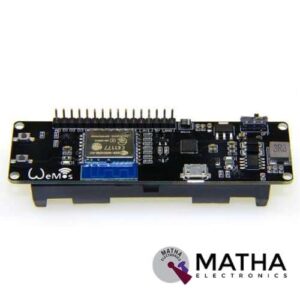
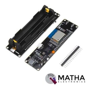
WeMos D1 ESP Wroom 02 Board ESP8266 Mini WiFi Nodemcu Module 18650 Battery
- One AD inputs.
- Micro USB inputs.
- One programmable LED (D0).
- AUTO PROGRAM circuit.
- ESP8266 (ESP-WROOM-02 With TELEC) is equivalent to the NodeMCU.
- Analog Input (AD): Built-in dividing resistor (AD = 220K ADC 100K = GND).
- There is a SOLDER terminal for SLEEP MODE.
- Compatible With Arduino andNodeMCU.
- Operation and charging are possible at the same time.
- 18650 charging circuit including the 5V boosting circuit with TP5410.
- Overcharge protection, over-discharge protection built-in.
- LED: Red = Charging, Green = Full charging.
- 3000 mA 18650 It is possible to operate for more than 17 hours on a battery.
- Integrated 18650 battery charging and discharging system.
- One switch controls whether the 18650 battery is on power or not.
- OLEDs SDA and SCL can connect to the D1 pin and the D2 pin respectively.
- The five buttons can be controlled by FLATH, RSET, D5, D6, and D7 respectively.
- The 5 Digital pins can configure the write/read/interrupt/PWM/I2C/one-wire supported separately.
- Operation and NodeMCU consistent, adding a programmable LED, you can use GPIO16 to control; display 8266 running status and other functions. Integrated OLED and five buttons, more convenient for development.
- The design concept originates from the open-source project NodeMCU; the development board integrates 18650 charging and discharging systems with charging and discharging protection. At the same time, an OLED and five directional buttons are integrated to facilitate the development.
Reviews
There are no reviews yet.