
I am text block. Click edit button to change this text. Lorem ipsum dolor sit amet, consectetur adipiscing elit. Ut elit tellus, luctus nec ullamcorper mattis, pulvinar dapibus leo.

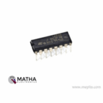
L293D Push-Pull Four Channel Driver IC
Original price was: ₹80.00.₹65.00Current price is: ₹65.00. inc. GST
L298N Dual Full-Bridge Driver IC
Original price was: ₹200.00.₹140.00Current price is: ₹140.00. inc. GST
L297 Stepper Motor Controller IC
- Stepper Motor Controller
- Half/Full Step Modes
- Clockwise/Anticlockwise Direction
- Switch Mode Load Current Regulation
- Programmable Load Current
- Supply Voltage: 10V
- Supply Current: 80mA
- Input Signals: 7V
- Total Power dissipation: 1W
- Output Voltage: 0.8V
- Package: DIP-20
Description
The L297 Stepper Motor Controller IC designed with four phase drive signals for two phase bipolar and four phase unipolar step motors in microcomputer-controlled applications. This motor has the capacity to drive in half step, normal and wawe drive modes. And also the two on-chip PWM chopper circuits permit switch-mode control of the current in the windings. This device requires only clock, direction and mode input signals. As the phase generated internally the load on the microprocessor, and the programmer, reduced greatly .
L297 Stepper Motor Controller IC easily mounted in DIP20 and SO20 packages. The L297 Stepper Motor Controller primarily intended for use with an L298N or L293E bridge driver. Or with discrete transistors and darlingtons in stepper motor driving applications. This IC accepts the control signals from the system’s controller, usually a microcomputer chip. And provides all the necessary drive signals for the power stage.
The L297 driver combination offers a wide range of advantages such as it requires only a few components. As a result, assembly costs remains low, reliability high, and little space required, also software development simplified and the burden on the micro reduced. Moreover, the choice of a two-chip approach gives a high degree of flexibility. L297 widely used with any power stage, including discrete power devices that provides 20mA drive for this purpose. The heart of the L297 is a block called the translator that generates suitable phase sequences for half step, one-phase-on full step and two-phase-on full-step operation. This block controlled via two mode inputs – direction (CW/ CCW) and HALF/ FULL – and a step clock that advances the translator from one step to the next.
Reviews (0)
Shipping & Delivery

Related products
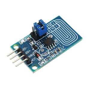
Capacitor Touch Dimmer, Constant Voltage LED Stepless Dimming, PWM Control Board
- Voltage range: 4V to 5V
- Maximum output current: 500mA
- Hole distance: 16 mm
- Aperture: 5 mm
- The lamp brightness can be adjusted by requirement, it is very to operate.
- It can touch in medium protection, such as glass, acrylic, plastic, ceramics, and so on, which is very safe.
- Anti power and phone interference, the EFT can reach above +/-2KV; the touch response sensitivity and reliability will not be affected by the close distance or multi-angle mobile phone interference.
- Dimming mode: Non-polar PWM dimming.
- PCB size: 23 x 20mm


MOTOR SHIELD L293
- 2 connections for 5V ‘hobby’ servos connected to the Arduino’s high-resolution dedicated timer
- 4 H-Bridges: L293D chipset provides 0.6A per bridge (1.2A peak) with thermal shutdown protection, internal kickback protection diodes.
- Can run motors on 4.5VDC to 25VDC.
- Up to 4 bi-directional DC motors with individual 8-bit speed selection (so, about 0.5% resolution)
- Up to 2 stepper motors (unipolar or bipolar) with single coil, double coil, or interleaved stepping.

NEMA 17 5.5 kgcm
- Step Angle : 1.8°
- Holding Torque : 5.5 KgCm
- Operating Voltage : 12 - 16 volts
- Supply Current (A) :1.5 Ampere
- Number of Leads : 6
- Inductance : 5.5 mH
- Resistance : 2.8 Ohms
- Weight (gm) : 363
- Detent Torque (kg-cm) : 2.6
- Frame Size (mm) : 42 x 42
- Inductance Accuracy : ±20%
- Resistance Accuracy : ±10%
- Step Angle Accuracy : ±5%
- Shaft Diameter (mm) : 5
- Shaft Length (mm) : 22
- Input pulse decides the rotation angle of the motor.
- High accuracy of around 3 to 5% a step.
- Provides good starting, stopping and reversing.
- Control of this motor is less costly because of exclusion of complex control circuitry.
- The speed is proportional to the frequency of the input pulses.
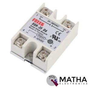
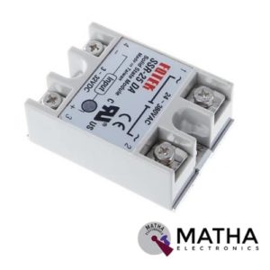
Solid State Relay Module SSR-25DA 25A /250V 3-32V DC Input 24-380VAC Output
- Control mode: DC-AC
- Input voltage: 3-32V DC.
- Output voltage: 24-380V AC.
- Output current: 25A.
- Working voltage: 250V.
- Material: plastic + metal.
- Environment temperature: -30 to +75
- Long service life and high reliability.
- Reduced electromagnetic interference.
- Highly reliable, compact size designed to offer users maximum simplicity.
- Dimension: 6. 5Cm x 4. 5Cm x 2. 2Cm

Stepper Motor Nema 23 kg 7.2 kg Dual shaft
- Rated Voltage: 6.6 V
- Current/ phase: 1A
- Resistance/ phase: 6.6ohms
- Inductance/ phase: 8.2 mH
- Holding Torque: 7.2 kg-cm
- of Leads - 6
- Rotor Inertia - 275
- Weight: 0.65kg
- Detent Torque: 0.36 kg-cm
- Step Angle - 1.8°
- Step Angle Accuracy - ±5% (full step, no load)
- Resistance Accuracy - ±10%
- Inductance Accuracy - ±20%
- Frame Size (mm) - 57x57
- Shaft Length (mm) - 20.6
- Shaft Diameter (mm) - 6.35
- Comparably more powerful than NEMA17 motors.
- Input pulse decides the rotation angle of the motor.
- High accuracy of around 3 to 5% a step.
- Provides good starting, stopping and reversing.
- Control of this motor is less costly because of exclusion of complex control circuitry.
- The speed is proportional to the frequency of the input pulses.
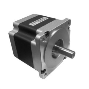
Stepper Motor NEMA 34 87 kg-cm Hybrid Bipolar
- Rated Voltage:4.2V
- Current/ phase: 5A
- Holding Torque: 87 kg-cm
- Number of Leads: 4
- Step Angle: 1.8°
- Step Angle Accuracy: ±5% (full step, no load)
- Resistance Accuracy: ±10%
- Inductance Accuracy: ±20%
- Frame Size: 85x85mm
- Shaft Length: 32mm
- Shaft Diameter: 12mm
- They are high torque stepper motors.
- Input pulse decides the rotation angle of the motor.
- High accuracy of around 3 to 5% a step.
- Provides good starting, stopping and reversing
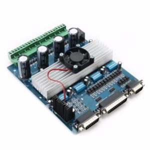
TB6560 4 Axis Cnc Controller 4 Axis Stepper Motor Driver DSP Controlled 3.5A 24V
- Rated maximum output: ± 4.5A, 40V, Peak 5A, low output impedance, source 0.5?,
- the receiving end of 0.4?, low voltage shutdown, thermal parking and circulation.
- circuit protection. After I design, you can set the current output of 0.5A 1A 1.8A 2.5A.
- 3.3A 4A 4.5A to accommodate more and different motor Current.
- The drive is suitable software mach2, mach3, (mach3 have support WIN7 system), KCAM4 like.
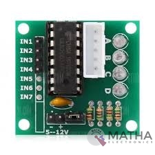
ULN2003 Driver
- Contains 7 high-voltage and high current Darlington pairs
- Each pair is rated for 50V and 500mA
- Input pins can be triggered by +5V
- All seven Output pins can be connected to gather to drive loads up to (7×500mA) ~3.5A.
- Can be directly controlled by logic devices like Digital Gates PIC etc
- Available in 16-pin DIP, TSSOP, SOIC packages
- Dimensions: 32 x 18 x 11mm (LxWxH)
- Weight: 3 gm
Reviews
There are no reviews yet.