
I am text block. Click edit button to change this text. Lorem ipsum dolor sit amet, consectetur adipiscing elit. Ut elit tellus, luctus nec ullamcorper mattis, pulvinar dapibus leo.
-14%
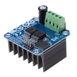
BTS7960 43A High Power Motor Driver Module/Smart Car Driver Module for Arduino Current Limit
Original price was: ₹1,500.00.₹950.00Current price is: ₹950.00. inc. GST
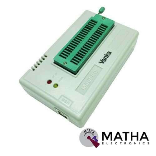
TL866CS USB Universal Programmer EEPROM FLASH 9 Adapters Extractor for 13000 Ics
Original price was: ₹7,525.00.₹5,000.00Current price is: ₹5,000.00. inc. GST
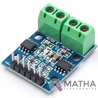
L9110 DC Stepper Motor Driver Board H-Bridge
Original price was: ₹350.00.₹300.00Current price is: ₹300.00. inc. GST
- Low static work current
- Power supply voltage: DC2.5-12V
- Each channel has 800mA continuous current output
- Low saturation pressure drop
- TTL/CMOS output level compatible can be connected directly to the CPU
- Output built-in clamping diode, apply to the perceptual load
- Control and drive integrated into IC
- Have pin high-pressure protection function
- Working temperature: 0-80 °C
Description
The L9110S dual-channel h-bridge motor driver module designed as a compact board used to drive small robots. This module based on the L9110 Motor Driver IC. This L9110S dual-channel H-bridge motor driver consists of two independent motor driver chips in which each capable of driving a continuous current up to 800mA. The boards operate at a voltage range from 2.5 V to 12 V enabling this module to used with both 3.3 Volts and 5 Volts microcontrollers. A set of female header pins provided to connect this module to a microcontroller. The motors easily attached via two sets of screw terminals.
The speed of the motor is controlled by a PWM Pulse Width Modulation signal and a digital output is used to change its direction. This module also used to drive a single four-line two-phase stepper motor. This module can be easily mounted onto your robot or other projects via four holes provided on the board.
Instructions:
- VCC external 2. 5V-12V voltage, GND external GND
- IA1 external MCU 10 port
- IB1 external MCU 10 port
- IA2 external MCU 10 port
- IB2 external MCU 10 port
- 0A1, 0B1 connected to 2 pins of DC motor, no direction
- 0A2, 0B2 connected to 2 pins of DC motor, no direction
- Turn on VCC, the GND module power indicator is on.
- IA1 input high level, IB1 input low level, [0A1 0B1] motor forward
- IA1 input low level, IB1 input high level, [0A1 0B1] motor reverse
- IA2 input high level, IB2 input low level, [0A2 0B2] motor forward
- IA2 input low level, IB2 input high level, [0A2 0B2] motor reverse
Reviews (0)
Shipping & Delivery

Related products

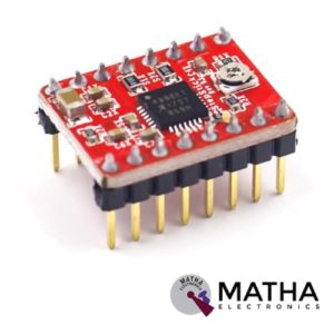
A4988 Stepper Motor
- Operating voltage supply: 8 V to 35 V
- Continuous current per phase: 1 Amp
- Maximum current per phase: 2 Amp
- Minimum logic voltage: 3V
- Maximum logic voltage: 5.5V
- Microstep resolutions: Full, 1/2, 1/4, 1/8, and 1/16
- Logic Voltage supply: 3.3 V to 5 V
- Compatible with 3V3 and 5V microcontrollers
- Our Board comes with 0.1 Ohm Sensor resistors
- Five different step resolutions: full-step, half-step, quarter-step, eighth-step, and sixteenth-step
- The Correct current decay mode (fast decay or slow decay) is selected by chopping the control
- Over-temperature thermal shutdown, under-voltage lockout, and crossover-current protection
- Short-to-ground and shorted-load protection
- 4-layer, 2 oz copper PCB for improved heat dissipation
- Exposed solderable ground pad below the driver IC on the bottom of the PCB

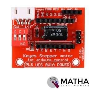
A4988 STEPPER MOTOR DRIVE CONTROLLER BOARD
- Operating voltage supply: 8 V to 35 V
- Continuous current per phase: 1 Amp
- Maximum current per phase: 2 Amp
- Minimum logic voltage: 3V
- Maximum logic voltage: 5.5V
- Microstep resolutions: Full, 1/2, 1/4, 1/8, and 1/16
- Compact size, easy to install and use.
- All jumpers hit the ON position to indicate 16 subdivisions (4988) or 32 subdivisions (8825).
- Jm connection motor; Jv Connects 5V and 12V-24V Power Supply.
- E /S /D /G of Jc corresponds to Enable /Step /Dir /Gnd driving signal output on the connection respectively.
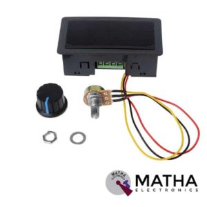

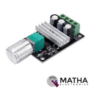
DC 6-30V 6V 12V 24V 5A PWM Motor Speed Controller with Digital Display
- Material: ABS
- Colour: Black
- Input power supply voltage: 6V-30V DC
- Output current: rated current 5A (maximum 8A, can not be extended)
- PWM frequency: 13kHz
- Duty cycle adjustable: 0%-100%
- Adjustable speed range: 0%-100%
- Fine workmanship and good performance.
- Digital display for duty ratio input
- Easy to use.
- Long service life.
- Suitable for the DC motor (or DC load) within 5A, Peak current 8A.
- Dimension: 78*42*25mm
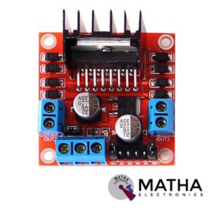

L298N MOTOR DRIVER
- Driver model: L298N 2A
- Driver chip: Double H bridge L298N
- Motor supply voltage: 46V(maximum)
- Motor supply current: 2A(maximum)
- Logic voltage: 5v
- Driver voltage: 5V-35V
- Driver current: 2A
- Logical current: 0-36mA
- Maximum power: 25W
- Current sensor for each motor
- LED indication for power status
- Heat sink for better performance
- Operating temperature: -25 degrees to 135 degrees Celsius
- Can be interfaced with simple manual switches, TTL logic gates, relays, etc.
- Dimension: 55*60*30mm
- Weight: 33gm
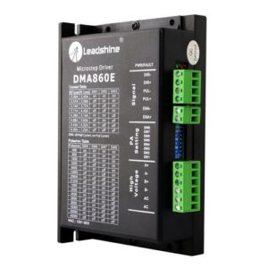
Leadshine DMA860E Stepper Motor Driver
- Model: DMA860E.
- Control Mode: Step & Direction.
- Max Input Frequency: 200 kHz.
- Input Voltage Range: 18 - 80 VAC / 24 - 110 VDC.
- Suggested Power Supply Voltage Range: 36-90 VDC /24-60 VAC.
- Number of DIP Switch Resolution Configurations: 16.
- 16 selectable micro-step resolutions of 400-51,200 via DIP switches.
- 8 selectable output current settings of 2.4 – 7.2A via DIP switches.
- Logic Current Range: 7-16mA (10mA typical).
- Logic Voltage Range: 4-5 VDC for pulse active high (default), or 0-0.5V for pulse active low.
- Pulse enabled at: Rising edge.
- Idle Current Percentage: 50 %.
- Number of Digital Inputs: 3.
- Step Width: 2,500 ns.
- Minimal Direction Setup Time: 5,000 ns.
- Isolation Resistance: 500M Ohm..
- Ambient Temperature: 0-50°C.
- Humidity: 40–95% RH.
- Operating Temperature: 0-70°C.
- Vibration: 5.9 m/s2 Max.
- Motor auto-identification and parameter auto-configuration for optimal torque from wide-range motors.
- Step & direction (PUL/DIR) and CW/CCW (via internal jumper set) control. Step & direction by default Multi-Stepping for smooth motor movement.
- Opto Isolation for input control signals.
- Soft-start with no “jump” when powered on.
- Protections for over-voltage and over-current.
- Dimension: 5.94 X 3.82 X 2.24 Inches.
- Weight: 1.13 lbs.

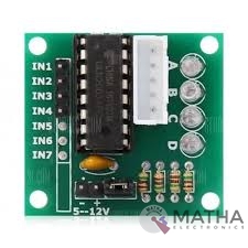
ULN2003 Driver
- Contains 7 high-voltage and high current Darlington pairs
- Each pair is rated for 50V and 500mA
- Input pins can be triggered by +5V
- All seven Output pins can be connected to gather to drive loads up to (7×500mA) ~3.5A.
- Can be directly controlled by logic devices like Digital Gates PIC etc
- Available in 16-pin DIP, TSSOP, SOIC packages
- Dimensions: 32 x 18 x 11mm (LxWxH)
- Weight: 3 gm
Reviews
There are no reviews yet.