
I am text block. Click edit button to change this text. Lorem ipsum dolor sit amet, consectetur adipiscing elit. Ut elit tellus, luctus nec ullamcorper mattis, pulvinar dapibus leo.
-17%Sold out

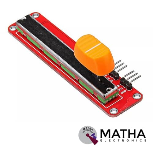
Double Analog Potentiometer Module With Slide Potentiometer Slip Adjustable Resistance For Arduino
Original price was: ₹300.00.₹250.00Current price is: ₹250.00. inc. GST
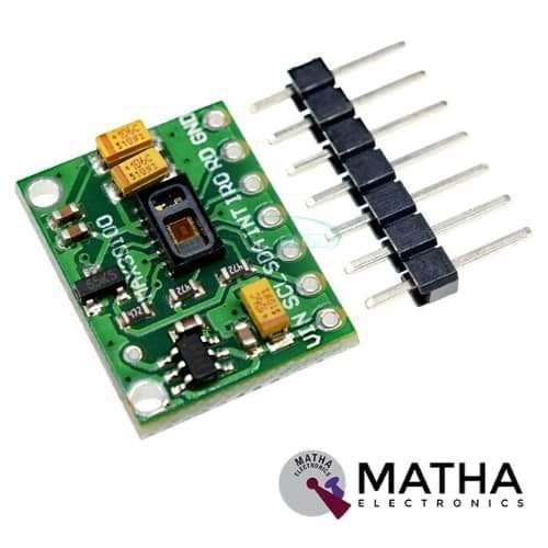
MAX30102 Heart Rate Oxygen Pulse Breakout Sensor Module For Arduino
Original price was: ₹500.00.₹450.00Current price is: ₹450.00. inc. GST
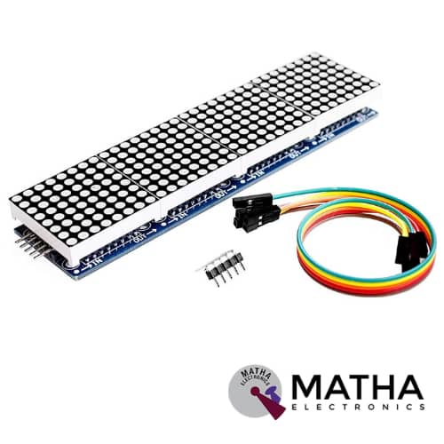
MAX7219 Dot Led Matrix Module 4 In 1 Display with 5P Line Module For Arduino Micro-controller
Original price was: ₹900.00.₹750.00Current price is: ₹750.00. inc. GST
- Driver Chip: MAX7219
- Input Voltage: 3.7 to 5.3 V
- Input Current: 320 mA
- Requires only 3 communication wires of MCU
- Pre-cascaded MAX7219 Dot Matrix LED Module.
- The overall size of the display is very compact
- With 64 fixing screw holes, hole diameter: 3mm.
- M3 holes for mounting.
- Module with input and output interfaces
- Support for cascading multiple modules
- Quite large display
- Display Dimensions: 32x32x6 mm
- PCD Dimensions: 128×32mm
- Weight: 55 gm
Out of stock
Description
This Dot Led Matrix Module incorporates the MAX7219 Driver chip designed based on an integrated serial input/output common-cathode display driver. This module interface with MPU to 7 segments LED display. This LED display is of up to 8 digits, bar-graph displays, or 64 individual LEDs. Max7219 consists of an on-chip BCD code decoder, multiplex scan circuitry, segment digits drivers, and an 8*8 static RAM. Hence, offers a slew rate, limited segment drivers, to reduce EMI. It requires only one external register to set the segment current of each LED.
The individual module features 8×8 LED’s, each controlled precisely by the MAX7219 driver to generate the colour pattern you wish. The great advantage of using this is users will have control over all of the 64 LED by just connecting 3 output communication wires to microcontrollers like Arduino etc. Thus all common micro-controllers communicate easily to this module by using a 4-wire serial interface. Each output can be addressed without refreshing the entire display. Using 3 I/O lines for driving the display, making it ideal for your microcontroller projects. Moreover, these 4 Dot Matrix LED’s cascaded to form a single LED Display to allot more area to the user on the display. Therefore, by simply connecting the output pins of the previous breakout board to the input pins of the new module, it is possible to connect as many DOT LED Modules to the Arduino.
Wiring Instructions:-
- Connect the left side of the module to the input port, the right to an output port.
- When the control of a single module, simply input port connected to CPU
- In cascaded modules, input and output termination CPU, an output terminal of the first module connected to the input terminal of the second module, the first two modules of the input terminal of the three termination modules, and so on.
Reviews (0)
Shipping & Delivery

Related products
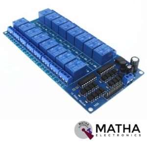
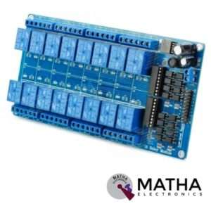
16 CHANNEL 5V RELAY
- 16 channel 5V relay board
- Operating voltage: 5V
- Supply current: 500mA
- Relay contact current capacity of 10A @250 V AC/10A@ 30V AC
- Optocoupler protection
- Low state voltage: 0V to 0.5V (relay is ON)
- High state voltage: 3.7V to 5V(relay is OFF)
- Single-chip design with reliable performance
- Strong anti-interferences
- Strong anti-jamming ability and stable performance
- The on-board power supply module doesn’t need any external power
- Common terminal(com) in each rely is user friendly and can be accessed by different signal
- Dimension: 180*90*20mm
- Weight: 100gm


3.3V/5V MB102 Breadboard Power Supply Module
- Input voltage: 6.5V to 12V
- Output voltage: 3.3V to 5V
- Output current: 700Ma
- Apply to MB102 breadboard
- Sorting jumpers used to switch voltage between 3.3V and 5V
- Onboard LED indicator to show the presence of power
- Short circuit protection
- Fits securely on standard 400 and 830 points on the breadboard
- Dimensions: 53*32*23mm
- Weight: 10gm
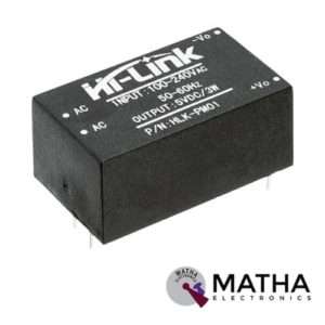
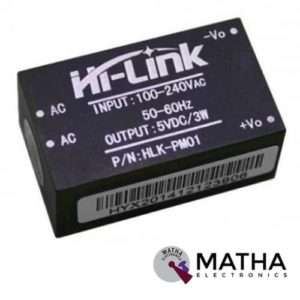
AC-DC Power Module HLK-PM01 230V to 5V /3W
- Meet UL, CE requirements
- Rated input voltage: AC 100V -230V
- Maximum input voltage: <270V AC
- Voltage Regulation: ±0.2%
- Load Regulation: ±0.5%
- High efficiency, high power density
- Ultra-thin and small module
- Low ripple and low noise
- Output overload and short circuit protection
- 100% load ageing and testing
- The product is designed to meet the requirements of the EMC and Safety Test
- Low power consumption, environmental protection, no-load loss <0.1W
- High efficiency, high power density
- Working temperature: – 20 degrees to +60 degrees Celsius
- Storage temperature: + 80-40 -degree
- Relative humidity: 5-95%
- Cooling way: Natural cooling
- Atmospheric pressure: 80-106Kpa
- Weight: 21g
- Size: 38x23x18mm
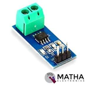

CURRENT SENSOR ACS712 30AMPS
- Current sensor chip: ACS712ELC-30A
- Supply voltage: 4.5V to 5.5V DC
- Current range: -30A to 30A
- Sensitivity: 66 millivolt/ampere
- Low noise analogue signal path
- Output rise time: 5 micro sec
- Extremely stable output offset voltage
- Zero magnetic hysteresis
- Factory trimmed for accuracy
- Easy to interface with a microcontroller, since it outputs an analogue voltage
- Onboard power indicator
- Dimension: 7*5*5cm
- Weight: 400gm

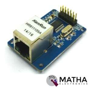
ENC28J60 ETHERNET MODULE
- ENC28J6 Ethernet chips, SOP28 package
- Operating voltage: 3.1V to 3.6V (3.3 V typical)
- Operating temperature: -40 degree to +85 degree Celsius
- IEEE 802.3 compatible Ethernet controller
- Buffer size: 8Kb
- Supports full and half-duplex mode
- SPI interface with a clock speeds up to 20MHz
- Programmable automatic rejection of erroneous packets
- Programmable automatic retransmit on a collision
- Programmable padding and CRC generation
- 25 MHz crystal oscillator
- Clock out the pin with a programmable presale
- Ethernet LAN module for Arduino/AVR/LPC/STM3
- 5V tolerant inputs
- SPI interface
- Led power indicator
- Dimension: 58*34*17mm

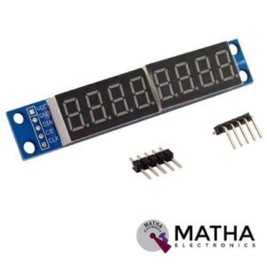
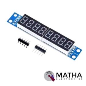
MAX7219 led module 8 digit 7 segment display
- Power: 5V
- Colour: Red/Blue (This colour means the colour of the board, not the LED)
- Material: PCB + Electronic Components
- MAX7219 digital display control module
- This module is compatible with 5V and 3.3V microcontrollers.
- You can use it for Arduino
- Only three IO ports are used to drive the eight-digit display. MAX7219 supports flicker-free displays as well as cascading displays.
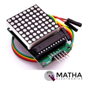
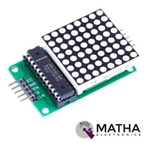
Square MAX7219 8×8 LED Dot Matrix Display Module
- Driver Chip: MAX7219
- Input Voltage: 3.7 to 5.3 V
- Input Current: 320 mA
- Display Dimensions: 32x32x6 mm
- PCD Dimensions: 50×32 mm
- A single module can drive an 8 * 8 common cathode lattice
- Requires only 3 communication wires of MCU
- Cascading multiple Matrix LED Module is very easy
- The size of the display is very compact
- The PCB features M3 holes for mounting.
Reviews
There are no reviews yet.