
I am text block. Click edit button to change this text. Lorem ipsum dolor sit amet, consectetur adipiscing elit. Ut elit tellus, luctus nec ullamcorper mattis, pulvinar dapibus leo.
-9%
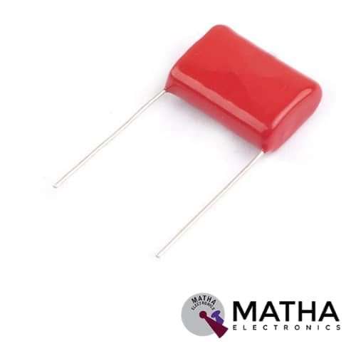
1.5uf 630V DC Polyester Capacitor
Original price was: ₹22.00.₹15.00Current price is: ₹15.00. inc. GST

MIP2C4 Power Device IC
Original price was: ₹75.00.₹65.00Current price is: ₹65.00. inc. GST
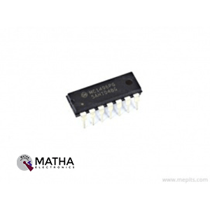
MC1496PG Balanced Modulator Demodulator IC
Original price was: ₹53.00.₹48.00Current price is: ₹48.00. inc. GST
- Balanced Modulator/Demodulator
- Differential Input Signal: 5V
- Maximum Bias Current: 10mA
- Carrier Suppression: 65dB
- Input Bias Current Max: 30µA
- Input Offset Current Max: 7µA
- Output Offset Current Max: 80µA
- Power Dissipation: 33mW
- Package: DIP-14
Description
The MC1496PG Balanced Modulator Demodulator IC is designed for applications where the output voltage is the result of a combination of an input voltage (signal) and a switching function (carrier). It may be used for suppressed carrier and amplitude modulation, synchronous detection, FM detection, phase detection, and chopper applications, among other things. An upper quad differential amplifier is powered by a normal differential amplifier with twin current sources in this design. The output collectors are cross coupled, allowing for full wave balanced multiplication of the two input voltages. That is, the output signal is the product of the two input signs multiplied by a constant.
For the carrier and signal voltage levels provided, carrier suppression is defined as the ratio of each sideband output to carrier output. It is very reliant on the carrier input level. Low carrier values don’t fully switch the upper switching devices, resulting in reduced signal gain and, as a result, lesser carrier suppression. A higher than optimal carrier level causes unnecessary device and circuit carrier feedthrough, causing the suppression figure to degenerate once again. A 60 mVrms sinewave carrier input signal was used to characterize the MC1496. This level is often chosen for balanced modulator applications because it gives the best carrier suppression at carrier frequencies around 500 kHz.
The MC1496 requires three externally controlled dc bias voltage values. Maintaining at least 2.0 V collector base bias on all transistors while not exceeding the voltages shown in the absolute maximum rating table are guidelines for setting up these three levels.
- 30 Vdc >= [(V6, V12) − (V8, V10)] >=2 Vdc
- 30 Vdc >= [(V8, V10) − (V1, V4)] >=2.7 Vdc
- 30 Vdc >= [(V1, V4) − (V5)] >=2.7
Reviews (0)
Shipping & Delivery

Related products


650NM Laser Diode
- Wavelength: 650nm
- Output optical power: 5mW
- Operating voltage: 5V
- Operating current: ~30mA
- Input current: 30mA
- Housing material: Copper
- Power lead length: 120mm.
- Transmit power: 58mW
- Spot: size 10mm to 15mm at 15meters
- Life span more than 2000 hours
- Driver circuit: APC circuit
- Small size
- Cost-effective
- Breadboard friendly
- Operating temperature -10°C to 40°C
- Dimension: :15mm x 6mm
- Weight: 10 grams
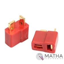
Dean Connector
- Male plug size: About 13* 7* 19mm
- Female plug size: About 13* 7* 15mm
- Current Rating: 30Amps
- Colour: Red and golden
- Material: Plastic and metal
- Provides a secure connection for battery and motor connections
- Eliminates the possibility of wrong polarity connections
- Used in RC hobby, car, boat, plane, helicopter, LIPO battery, etc.
- Dimension: 9x0.7x2cm
- Weight:20gm


Dual Micro USB 3.7v to 5V 2A Power Bank DIY 18650 LiPo Charger
- 4-level LED lamp display power, not working state intelligent automatic shutdown;
- The built-in lithium battery protection IC, over-current, under-voltage protection;
- Dual USB output ports.
- Dimensions: 68 x 34 x 9 mm (LxWxH)
- Weight: 10 gm
- Input port: MicroUSB (Andro)
- Input requirements: 5V constant voltage power supply can do charge input power, the most matching charger for 5v1a above
- Output port: USB
- Output parameters: 5V1A/5V2A
- Requirements for rechargeable batteries:
- Compatible Batteries: 18650 batteries, cell phone batteries, flat-panel batteries, MP3 batteries, etc. 3.7v-4.2V polymer Lithium battery,
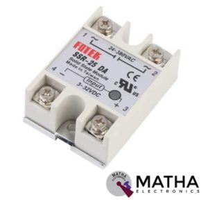
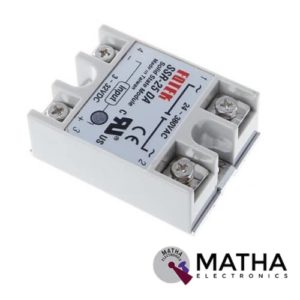
Solid State Relay Module SSR-25DA 25A /250V 3-32V DC Input 24-380VAC Output
- Control mode: DC-AC
- Input voltage: 3-32V DC.
- Output voltage: 24-380V AC.
- Output current: 25A.
- Working voltage: 250V.
- Material: plastic + metal.
- Environment temperature: -30 to +75
- Long service life and high reliability.
- Reduced electromagnetic interference.
- Highly reliable, compact size designed to offer users maximum simplicity.
- Dimension: 6. 5Cm x 4. 5Cm x 2. 2Cm
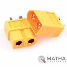
XT60 Connector
- Manufacturer: AMASS
- Connector Series: XT60H
- Rated Voltage: DC 500V
- Metal Material: Brass Gold Plated
- Rated Current: 30A
- Momentary Current: 60A
- Number of pins: 2
- Colour: Yellow
- Contact Resistance: 0.55mΩ
- FR Level: UL94 V0
- Use Times: 1000 TIMES
- Temperature: -20℃ to 120℃
- Spatial Orientation Straight
- Compatible for Wire size up to 12AWG
- Mechanical mounting for cable
- Electrical mounting soldered
- Contact plating Gold flash
Reviews
There are no reviews yet.