
I am text block. Click edit button to change this text. Lorem ipsum dolor sit amet, consectetur adipiscing elit. Ut elit tellus, luctus nec ullamcorper mattis, pulvinar dapibus leo.
-9%
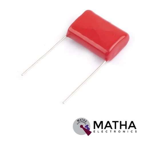
1.5uf 630V DC Polyester Capacitor
Original price was: ₹22.00.₹15.00Current price is: ₹15.00. inc. GST

MIP2C4 Power Device IC
Original price was: ₹75.00.₹65.00Current price is: ₹65.00. inc. GST
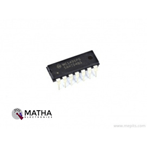
MC1496PG Balanced Modulator Demodulator IC
Original price was: ₹53.00.₹48.00Current price is: ₹48.00. inc. GST
- Balanced Modulator/Demodulator
- Differential Input Signal: 5V
- Maximum Bias Current: 10mA
- Carrier Suppression: 65dB
- Input Bias Current Max: 30µA
- Input Offset Current Max: 7µA
- Output Offset Current Max: 80µA
- Power Dissipation: 33mW
- Package: DIP-14
Description
The MC1496PG Balanced Modulator Demodulator IC is designed for applications where the output voltage is the result of a combination of an input voltage (signal) and a switching function (carrier). It may be used for suppressed carrier and amplitude modulation, synchronous detection, FM detection, phase detection, and chopper applications, among other things. An upper quad differential amplifier is powered by a normal differential amplifier with twin current sources in this design. The output collectors are cross coupled, allowing for full wave balanced multiplication of the two input voltages. That is, the output signal is the product of the two input signs multiplied by a constant.
For the carrier and signal voltage levels provided, carrier suppression is defined as the ratio of each sideband output to carrier output. It is very reliant on the carrier input level. Low carrier values don’t fully switch the upper switching devices, resulting in reduced signal gain and, as a result, lesser carrier suppression. A higher than optimal carrier level causes unnecessary device and circuit carrier feedthrough, causing the suppression figure to degenerate once again. A 60 mVrms sinewave carrier input signal was used to characterize the MC1496. This level is often chosen for balanced modulator applications because it gives the best carrier suppression at carrier frequencies around 500 kHz.
The MC1496 requires three externally controlled dc bias voltage values. Maintaining at least 2.0 V collector base bias on all transistors while not exceeding the voltages shown in the absolute maximum rating table are guidelines for setting up these three levels.
- 30 Vdc >= [(V6, V12) − (V8, V10)] >=2 Vdc
- 30 Vdc >= [(V8, V10) − (V1, V4)] >=2.7 Vdc
- 30 Vdc >= [(V1, V4) − (V5)] >=2.7
Reviews (0)
Shipping & Delivery

Related products


25pcs Button Switch Kit
- Relative Humidity: 95%
- Rated Voltage: 12V
- Rated Current: 50 mA
- Contact resistance: 50M Ohm Max (initial)
- The insulation resistance: 100M Ohm minDC (250V)
- The compressive strength: AC250V (50/60Hz for 1 minute)
- Mechanical life: 100000 cycles
- The environment temperature: 25° ~ + 105°
- The operating strength: 180/250 (plus or minus 30gf)
- Dimension: 12 * 12 * 7.3 round convex type
- Total Buttons: 25pcs
- Colours: 5 (Black, Red, White, Blue, Yellow)
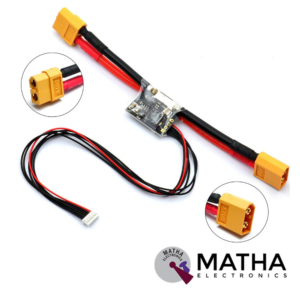
APM/Pixhawk Power Module V6.0 Output BEC 3A XT60 Plug 28V 90A
- Input Voltage Range: 6-28V DC
- Output voltage: 5.3V ± 0.1V
- Maximum output current: 3A
- Maximum current: 90A
- Maximum voltage: 30V
- Supports from 2 cell to 6 cell battery.
- 6P cable can be directly connected to APM/Pixhawk flight control
- Additional 4P rows of pin-free to wire/PIN to connect to another flight control
- Voltage and current measurement configured for 5V ADC.
- Switching regulator outputs 5.3V and 3A max.
- Dimensions: 25mm x 21mm x 9mm
- Weight: 17gm


Dual Micro USB 3.7v to 5V 2A Power Bank DIY 18650 LiPo Charger
- 4-level LED lamp display power, not working state intelligent automatic shutdown;
- The built-in lithium battery protection IC, over-current, under-voltage protection;
- Dual USB output ports.
- Dimensions: 68 x 34 x 9 mm (LxWxH)
- Weight: 10 gm
- Input port: MicroUSB (Andro)
- Input requirements: 5V constant voltage power supply can do charge input power, the most matching charger for 5v1a above
- Output port: USB
- Output parameters: 5V1A/5V2A
- Requirements for rechargeable batteries:
- Compatible Batteries: 18650 batteries, cell phone batteries, flat-panel batteries, MP3 batteries, etc. 3.7v-4.2V polymer Lithium battery,

HX711–24 Bit Analog to Digital Converter (ADC)
- It is an ADC converter with two differential input channels
- An active-low noise PGA is integrated inside the chip which provides the gain of 32, 64 and 128
- It has a power-on-reset capability which simplifies digital interface initialization.
- All controls to the IC are made through the pins. Programming is not needed.
- You can select a data rate of 10SPS or 80SPS at the output.
- Provides simultaneous supply rejection of 50Hz and 60Hz supply.
- Built-in analog power supply regulator
- The voltage supply range is from 2.6V to 5.5V
- The temperature range is from -40 °C to +85℃
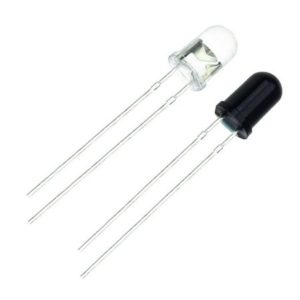
IR LED Sensor
- Size: 5mm LED
- Wavelength: 940nm wavelength (most commonly used)
- Forward current (IF) is 100mA (normal condition) and 300mA (max.)
- 5A of surge forward current
- 24v to 1.4v of forward voltage
- Temperature : -40 to 100 ℃
- Soldering Temperature should not exceed 260 ℃
- Power Dissipation of 150mW at 25℃ (free-air temperature) or below
- Spectral bandwidth of 45nm
- Viewing angle: 30 to 40 degree
- High Reliability
- Excessive radiant intensity
- Having lead spacing of 2.54mm
- Easy to use with breadboard or perf board

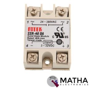
Solid State Relay Module DC To AC SSR-40DA 3-32VDC/24-380VAC 40A
- Control mode: DC-AC
- Input voltage: 3-32V DC.
- Output voltage: 24-380V AC.
- Output current: 40A.
- Working voltage: 250V.
- Material: plastic + metal.
- Loading current: 40A
- Control current: 3-25mA DC
- On voltage: ≤1.5V AC
- One-off Time: ≤10ms
- Off Leakage Current: ≤2mA
- Dielectrics voltage-resistance: 2500VAC
- Environment temperature: -30 to +75
- Long service life and high reliability.
- Reduced electromagnetic interference.
- Highly reliable, compact size designed to offer users maximum simplicity.
Reviews
There are no reviews yet.