
I am text block. Click edit button to change this text. Lorem ipsum dolor sit amet, consectetur adipiscing elit. Ut elit tellus, luctus nec ullamcorper mattis, pulvinar dapibus leo.


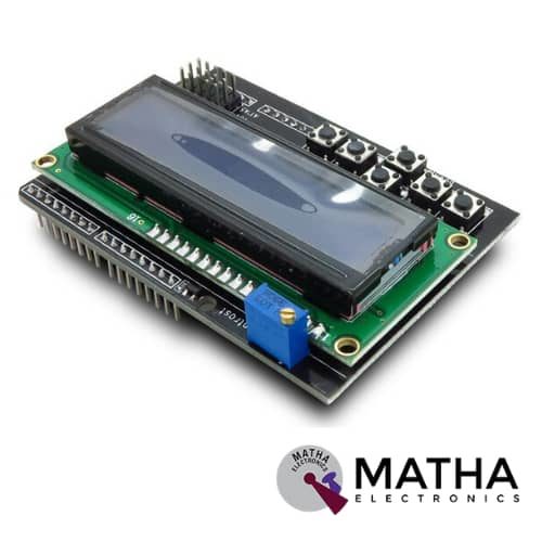
16x2 (1602) LCD Keypad Shield
Original price was: ₹450.00.₹400.00Current price is: ₹400.00. inc. GST
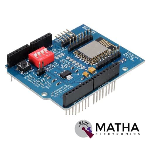
ESP8266 WIFI Shield
Original price was: ₹935.00.₹899.00Current price is: ₹899.00. inc. GST
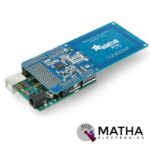
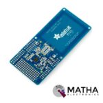
PN532 NFC/RFID Controller Shield for Arduino
₹1,500.00 inc. GST
- PN532 chip-set
- Operating Voltage : 3.3V ~ 5v
- Support I2C, SPI
- I2C: 3.3V ~ 24V TTL
- SPI: 3.3V TTL with 100-ohm resistors in series
- Plug and play, Arduino compatible
- Built-in PCB Antenna
- Communication distance:10cm
- Easy to change mode
- NFC/RFID PN532 shield including a tuned 13.56MHz stripline antenna
- 36-pin 0.1″ header for attaching the shield to an Arduino.
- Compatible with Arduino Mega 1280 & 2560, Diecimila, Duemilanove, and UNO
Description
NFC/RFID Sheild was designed as a perfect tool for any 13.56MHz RFID or NFC application. This NFC shield uses the PN532 chip set. PN532 NFC Module was designed as a highly integrated radio transmission module for Near Field Communication at 13.56MHz. NFC protocol designed for smartphones and similar devices, can read and write cards and tags, interact with NFC phones, and enable communication from device to device. While the controller provides many capabilities. Our Arduino library currently only supports reading/writing tags and does not support phone-to-shield communication, tag emulation (which requires an external ‘secure element’ only available from NXP) or other more advanced features at this time.
This shield comes with a tuned 13.56MHz stripline antenna, 36-pin 0.1″ header for attaching the shield to an Arduino. In order to stack another shield on top or below, stacking headers allow pass-through stacking. This shield was designed by RF engineers using the best test equipment to create a layout. And antenna within a range of 10cm (4 inches), the maximum range possible using the 13.56MHz technology. It is quite easy to attach the shield behind a plastic plate with standoffs and still read cards through a (non-metal) barrier.
This shield supports I2C or SPI communication protocols. I2C is the default, as it uses fewer pins. Analog pins 4 and 5 are used for I2C ( you can still connect other I2C devices to the bus). And Digital #2 is used for “interrupt” notification. This means we don’t have to sit there and ‘poll’ the chip to ask a target tag has been found. The pin will pull low when a card, phone, etc is within range. The shield changes over to SPI easily where you can use any 4 digital pins by shorting two solder jumpers on the top of the PCB. These NFC/RFID Compatible with any “classic” Arduino – NG, Diecimilla, Duemilanove, UNO – as well as Mega R3 or later.
Reviews (0)
Shipping & Delivery

Related products


2.4″ Inch Touch Screen TFT Display Shield for Arduino
- 4″ Touch LCD TFT display module for Arduino
- 240*320 pixels resolution
- Ability to display 262000 different colours
- The shield comes equipped with a microSD card slot.
- SPFD5408 controller with built-in video RAM buffer
- 8-bit digital interface, plus 4 control lines
- 5V compatible. Use with 3.3V or 5V logic
- On-board 3.3V 300mA LDO regulator
- Uses digital pins 5-13 and analogue 0-3. That means you can use digital pins 2, 3, and analog 4 and 5. Pin 12 is available if not using the microSD
- Works with any Arduino Uno and mega compatible boards
- Resolution: 240320 pixels
- Supply voltage: 5V
- Working temperature: -30C ~ 70C
- Dimension: 72*52*12mm

4*4 MATRIX KEYPAD
The maximum voltage across each button: 24v
- The maximum current across each button: 3mA
- Easy communication with any microcontroller
- Ultra-thin design
- Adhesive backing provides easy integration
- High price-performance ratio
- Allows microcontroller to scan 8 output pins to check which 16 button
- Long life
- Maximum operating temperature: 0 degrees to 50 degrees Celsius
- Dimension: 70*77*1mm
- Weight: 7.5gm
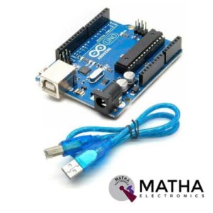

Arduino Duemilanove Development Board with USB Cable
- Microcontroller: ATmega168/ATmega 328
- Operating Voltage: 5V
- Input Voltage: 7-12V
- Input Voltage: 6-20V
- Digital I/O Pins: 14 (of which 6 provide PWM output)
- Analog Input Pins: 6
- DC Current per I/O Pin: 40 mA
- DC Current for 3.3V Pin: 50 mA
- Flash Memory: 16 KB (ATmega168) or 32 KB (ATmega328) of which 2 KB used by the bootloader
- SRAM: 1 KB (ATmega168) or 2 KB (ATmega328)
- EEPROM: 512 bytes (ATmega168) or 1 KB (ATmega328)
- Clock Speed: 16 MHz
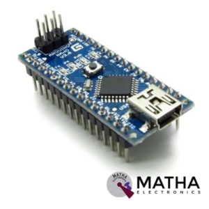

Arduino Nano V3.0
- Microcontroller: Atmel ATmega328 SMD Package
- Operating Voltage (logic level): 5 V
- Input Voltage (recommended): 7-12 V
- Input Voltage (limits): 6-20 V
- Digital I/O Pins: 14 (of which 6 provide PWM output)
- Analog Input Pins: 8
- DC Current per I/O Pin: 40 mA
- Flash Memory: 32 KB (of which 2KB used by bootloader)
- SRAM: 2 KB
- EEPROM: 1 KB
- Clock Speed: 16 MHz
- Automatic reset during program download
- Power OK blue LED
- Green (TX), red (RX) and orange (L) LED
- Auto-sensing/switching power input
- Small mini-B USB for programming and serial monitor
- ICSP header for direct program download
- Standard 0.1” spacing DIP (breadboard friendly)
- Manual reset switch
- Dimensions: 0.70” x 1.70”


DTMF Shield
- MT8870 Decoder IC.
- 4 Output digital pins.
- Operates on 5V
- Includes MT8870 DTMF Receiver IC
- Receives and Converts Standard DTMF Codes
- Remotely Switch Devices from Anywhere Using the Phone
- Easily Connects to Most Microcontrollers or Roboduino Board
- Low Power Consumption
- 5 On-Board LED's For Data Received Indication
- Standard Header Connections for Control System Connection
- Audio socket for application
- Speaker connector for audio sound checking.
- Microphone connector for over the air remote control system( note, due to environmental noise, without any filtering system this method is not recommended)
- Dimension: 37x37x9mm

MEPUNO COMMUNICATION BOARD
- Microcontroller ATMEGA328 P
- Crystal for microcontroller: 16 MHZ
- USB type B connector
- On-Board Power LED Indicator
- 5volt, 12 volt regulated circuit
- Two separate regulated 5volt power supply
- On Board On/Off switch
- On Board DC jack for powering up using adaptors
- On Board Reset Switch
- On Board TX/RX indication LEDs
- On board FTDI Driver for adruino
- Berg headers for external interfacing
- Supports I2C /GSM /GPS/RF/USART serial communication
- Separate berg headers available for PIR, Servo motor, RTC/I2C, GPS_TTL, and USART-TTL
- Four 3pin PBT Connectors
- Four SPDT 12V Relays
- Onboard DB9 connectors for GPS, GSM and USART communication
- Berg slot for 16x4 LCD connections
- Onboard TRIM-POT for LCD
- Onboard RTC IC: IN1307 with crystal 32768 MHZ crystal and CR2302 battery

STM32 Nucleo-64 development board with STM32F103RB MCU, supports Arduino and ST morpho connectivity
- STM32 microcontroller with LQFP64 package
- Two types of extension resources
- mbed-enabled (mbed.org)
- On-board ST-LINK/V2-1 debugger/programmer with SWD connector
- Flexible board power supply
- Three LEDs
- Two push buttons: USER and RESET
- USB re-enumeration capability: three different interfaces supported on USB
- Comprehensive free software HAL library including a variety of software examples
- Supported by wide choice of Integrated Development Environments (IDEs) including IAR, Keil, GCC-based IDEs
Reviews
There are no reviews yet.