
I am text block. Click edit button to change this text. Lorem ipsum dolor sit amet, consectetur adipiscing elit. Ut elit tellus, luctus nec ullamcorper mattis, pulvinar dapibus leo.
-13%


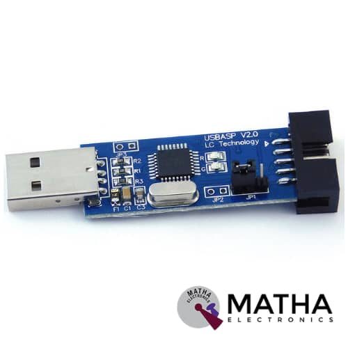
USBASP PROGRAMMER
Original price was: ₹450.00.₹399.00Current price is: ₹399.00. inc. GST
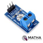
VOLTAGE SENSOR
Original price was: ₹150.00.₹130.00Current price is: ₹130.00. inc. GST
- Input voltage: 0-25v
- Divider ratio: 5:1
- Resistor Tolerance: 1%
- Resistor Value: 30K/7.5K Ohm
- Voltage detection range: 0.02445-25
- Analog voltage resolution: 0.00489v
- Wide operating range
- No external components required
- Compact size and high accuracy
- Weight: 4gm
- Dimension: 4*3*2cm
Description
A voltage sensor is a conventional method used to determine, monitor, and measure the supply of voltage in a device. Voltage sensors can sense both AC and DC voltages. Voltage sensors are highly precise sensors that work on the principle of the potential divider rule. As a result, it reduces the input voltage by a factor of 5. This allows us to use the analogue input pin of microcontrollers to observe the voltage above the threshold level. With a small compact device, both voltage and current measurement are combined to a single physical device. For 0-5v analogue input, the output measured up to 25v. A voltage sensor consists of 5 pins in which two of which are on the two-pin screw terminal and three are male header pins.
PIN DESCRIPTION
- VCC: Positive terminal of the voltage to be measured (0-25V)
- GND: Negative terminal of the voltage to be measured
- S: Analog Input of Arduino
- +: Not connected (N/C)
- –: GND of Arduino
The Interfacing of a voltage sensor with Arduino or any other microcontroller is quite simple. The VCC and GND of the voltage source are connected to the screw terminals of the voltage sensor. And the S and – (GND) pins are connected to the Analog pin and GND of Arduino respectively. Moreover, the screw terminals present in the module provide an easy and secure connection to a wire.
In a voltage sensor, Arduino AVR chips have 10-bit AD, thus it provides a resolution of 0.00489V (5V/1023). So the minimum voltage of the input voltage detection module is 0.00489Vx5=0.02445V.
Reviews (0)
Shipping & Delivery

Related products

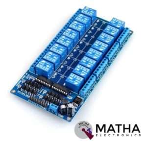
16 CHANNEL 12V RELAY
- 16 channel 12V relay board
- Operating voltage: 12V
- Supply current: 0.2 A
- Relay contact current capacity of 10A @250 V AC/10A@ 30V AC
- Optocoupler protection
- LED status indicates relay ON/OFF state.
- The 10-16 road can be any full-on/off or any road
- Common terminal(com) in each rely is user friendly and can be accessed by different signal
- Normally closed or normally open with each port
- Strong anti-jamming ability and stable performance
- The on-board power supply module doesn’t need any external power
- Dimension: 180*90*20mm
- Weight: 100gm
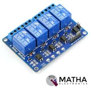

4 CHANNEL 5V RELAY
- 4-Channel relay interface board
- Operating voltage range: 3.3V to5V
- Maximum current: 10A
- Supply current: 20 mA
- High current relay of 10A @250 V AC/10A@ 30V DC
- Control signal: TTL level
- For quick and easy connection high-quality screw terminals provided
- Pull-down circuit to avoid malfunction
- Power supply indicator
- Can control both AC & DC appliances such as DC motors, solenoid valves, lamps, etc.
- LED status indicates relay ON/OFF state.
- Standard interface that can be controlled by a microcontroller (Arduino, 8051, PIC, AVR, DSP, ARM)
- For easy accessibility input signal pin connected to burg sticks
- Operating temperature: -40 to 85 degrees Celsius
- Dimension: 76*56*17mm
- Weight: 7gm
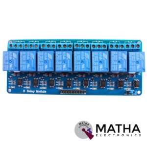
8 CHANNEL 5V RELAY
- Relay operating voltage: 5V
- 8 channel
- High impedance controller pin
- One normally closed contact and one normally opened
- Useful for appliances control
- Power supply indicator and control indicator lamp
- Pull-down circuit to avoid malfunction
- Can control both DC and AC to 220v AC load
- Works with both 3.3 V and 5 V logic with the less current drive
- 3 terminals per SPDT relay
- Standard interface can be directly controlled by a microcontroller like Arduino, 8051, AVR, PIC, DSP, ARM, MSP430, TTL logic
- Dimension: 7*6.4*1 inch

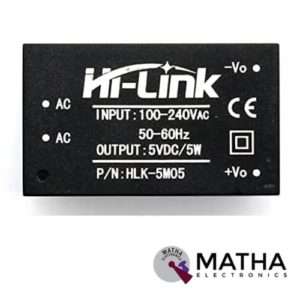
AC-DC Power Module HLK-5M05 230V to 5V /5W
- Meet UL, CE requirements
- Rated input voltage: AC 100V -230V
- Input voltage range: 90V -264V AC
- Maximum input current: <0.2A
- Input current surge: <10A
- Maximum input voltage: <270V AC
- Input Low Voltage Efficiency: Vin=110V AC,Output full-load≥ 69%
- Input High Voltage Efficiency: Vin=220V AC,output full-load≥ 70 %
- Long-term reliability
- Voltage Regulation: ±0.2%
- Load Regulation: ±0.5%
- Ultra-thin and small module
- High efficiency, high power density
- Low ripple and low noise
- Output overload and short circuit protection
- Working temperature: – 20 degrees to +60 degrees Celsius
- Storage temperature: -40 degrees to 80 degrees Celsius
- Relative humidity: 5-95%
- Cooling way: Natural cooling
- Atmospheric pressure: 80-106Kpa
- Weight: 21g
- Size: 38x23x18mm
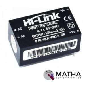

AC-DC Power Module HLK-PM12 230V to 12V /3W
- Rated input voltage: AC 100V -230V
- Input voltage range: 90V -264V AC
- Maximum input current: <0.2A
- Input current surge: <10A
- Maximum input voltage: <270V AC
- Input Low Voltage Efficiency Vin=110V AC,Output full-load≥ 69%
- Input High Voltage Efficiency Vin=220V AC,output full-load≥ 70 %
- Short-term maximum output current: ≥1000 mA
- Long-term reliability
- Voltage Regulation: ±0.2%
- Load Regulation: ±0.5%
- Ultra-thin and small module
- High efficiency, high power density
- Low ripple and low noise
- Output overload and short circuit protection
- Working temperature: – 20 degrees to +60 degrees Celsius
- Storage temperature: -40 degrees to 80 degrees Celsius
- Relative humidity: 5-95%
- Cooling way: Natural cooling
- Atmospheric pressure: 80-106Kpa
- Weight: 21g
- Size: 38x23x18mm


IRF520 MOSFET DRIVER MODULE SENSOR
- Operating Voltage: 3.3v & 5v
- Digital level port
- Output load voltage: 0-24v
- Output load current: <5A
- The heat sink is added for currently more than 1A
- Compatible with Arduino, MCU, ARM, Raspberry pi
- PWM dimming LED used to step-less dimming, variable-speed motor
- Output PWM can be adjusted by the original IFR520 MOS
- Arduino can drive up to 24V, such as led lights, dc motors, miniature pumps, solenoid valves etc.
- Dimension:34*30*18mm
- Size: 10gm

Reviews
There are no reviews yet.