
I am text block. Click edit button to change this text. Lorem ipsum dolor sit amet, consectetur adipiscing elit. Ut elit tellus, luctus nec ullamcorper mattis, pulvinar dapibus leo.
Sold out

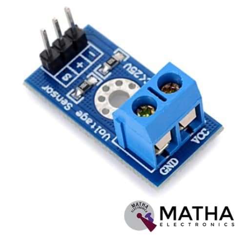
VOLTAGE SENSOR
Original price was: ₹150.00.₹130.00Current price is: ₹130.00. inc. GST
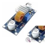
XL4015 5A STEP DOWN MODULE
Original price was: ₹700.00.₹450.00Current price is: ₹450.00. inc. GST
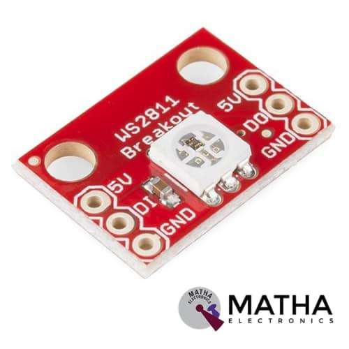
WS2812 LED BREAKOUT BOARD
- Input Voltage: -0.5~VDD+0.5V
- Supply voltage: 5v
- Operating voltage: 4v -7v
- Integrating control circuit and RGB chip
- Built-in signal reshaping circuit
- Built-in electric reset circuit and power lost reset circuit
- 256 brightness and 16777216 colour display
- Viewing angle: 120 degree
- Cascading port transmission signal
- Red Vf: 1.8~2.2V
- Green Vf: 3.0~3.2v
- Blue Vf: 3.2~3.4V
- Red Wavelength: 620~630 nm
- Green Wavelength: 515~530 nm
- Blue Wavelength: 465~475 nm
- Red luminous intensity(20mA): 550~700mcd
- Green luminous intensity(20mA): 1100~1400mcd
- Blue luminous intensity(20mA): 200~400mcd
- Dimension: 1.8*1.3*0.8mm
Description
WS2812 is the heart and soul of various products in an electronics system. This is a breakout board designed for WS2812 RGB Led with an integrated WS2811 control IC embedded right into the LED. Here the control IC of an adjustable RGB LED is hidden under the actual LED. All the pins are arranged as 0.1 spaced headers for easy breadboarding. The controller IC communicates with the LED via a one-wire interface. When the output of one LED is connected to the input of others creates a strip of many LEDs. Thus the connection of several breakout boards can form a display. The breakout board produces an output current of 60mA producing 20mA by each colour channel. After being connected in series, each light in the breakout board can control the colour separately.
WS2812 breakout board consists of an intelligent digital port data latch and signal reshaping amplification drive circuit. Also include a precision internal oscillator and a 12V voltage programmable constant current control part, ensuring the pixel point light colour height is consistent. When the pixel power is reset, the DIN port receives data from the controller. Thus the first pixel collects the initial 24bit data and sent it to the internal data latch. The signal reduces to 24bit, after the transmission of each pixel. The internal signal reshaping amplification circuit reshapes the other data and sent it to the next cascade pixel through the DO port. Here the data transfer protocol uses a single NZR communication mode.
Applications
- Full-colour soft lights lamp strip.
- LED decorative lighting
- Indoor/outdoor LED video irregular screen.
Reviews (0)
Shipping & Delivery

Related products


10D OF 9-AXIS GY-87
- Power supply: DC 3.3V TO 5V
- 3 Axis Gyro+ Acceleration+ Magnetic field
- Air pressure module
- Inbuilt ultra-low noise linear LDO voltage regulator
- Inbuilt onboard filters. which reduce noise from motor and another high current
- Communication: I2C protocol
- Power LED
- Designed for 5V logic
- Can easily select two I2C addresses for MPU6050 by soldered jumper
- Dimension: 2.2*1.7cm
- Size: 6gm


3.3V/5V MB102 Breadboard Power Supply Module
- Input voltage: 6.5V to 12V
- Output voltage: 3.3V to 5V
- Output current: 700Ma
- Apply to MB102 breadboard
- Sorting jumpers used to switch voltage between 3.3V and 5V
- Onboard LED indicator to show the presence of power
- Short circuit protection
- Fits securely on standard 400 and 830 points on the breadboard
- Dimensions: 53*32*23mm
- Weight: 10gm


4*3 MATRIX KEYPAD
- Operating voltage: 12V DC
- The maximum voltage across each button: 24v
- The maximum current across each button: 3mA
- Ultra-thin design
- Adhesive backing provides easy integration
- Easy communication with any microcontroller
- Flexible
- Only 7 microcontroller pins required to access 12 keys
- High price-performance ratio
- Allows microcontroller to scan 8 output pins to check which 16 button
- Long life
- Maximum operating temperature: 0 degrees to 50 degrees Celsius
- Dimension: 70*77*1mm
- Weight: 7.5gm
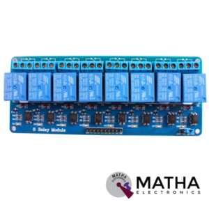
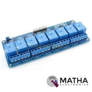
8 CHANNEL 5V RELAY
- Relay operating voltage: 5V
- 8 channel
- High impedance controller pin
- One normally closed contact and one normally opened
- Useful for appliances control
- Power supply indicator and control indicator lamp
- Pull-down circuit to avoid malfunction
- Can control both DC and AC to 220v AC load
- Works with both 3.3 V and 5 V logic with the less current drive
- 3 terminals per SPDT relay
- Standard interface can be directly controlled by a microcontroller like Arduino, 8051, AVR, PIC, DSP, ARM, MSP430, TTL logic
- Dimension: 7*6.4*1 inch


DS3231 RTC MODULE
- Operating voltage of DS3231: 2.3 v to 5.5v
- 400Khz I2C interface
- Automatic power failure battery switch circuitry
- RTC counts seconds, minutes, hours, and year
- High precision clock chip DS3231
- Programmable square-wave output
- Chip temperature sensor accuracy:+/_3 degree Celsius
- Memory chip: AT24C32 with 32K storage capacity
- CR2032 battery backup with a high life span
- Low power consumption
- Register for ageing trim
- Dimension: 38mm*22mm*14mm


ISD1820 MODULE (10 SEC)
- Operating voltage: 2.6v to 5v
- Record and playback up to 10 sec
- Push-button and microcontroller controllable AGC circuit added tom increase audio playback volume
- Recording time: 8- 20 sec
- Built-in microphone
- On-chip 8-ohm speaker driver
- High quality, natural voice restored
- Available single-chip control audio recording control mode: the key to control or microcontroller, IO has drawn the line of control
- Can be used as propaganda module
- Auto power down mode
- Duration and sample rate can be extended to 20 sec by varying resistance
- Dimension: 43*34*11mm

Reviews
There are no reviews yet.