
To execute any useful operation or function, an electronic circuit or system must be able to communicate with the “real world,” whether by reading an input signal from an “ON/OFF” switch or by activating some type of output device to illuminate a single light.
In other words, an Electronic System or circuit must be able to “do” something, and Sensors and Transducers are ideal components for this purpose. The name “Transducer” refers to both Sensors and Actuators. Sensors are used to detect a broad variety of energy forms, such as motion, electrical signals, radiant energy, thermal or magnetic energy, etc., while Actuators are used to switch voltages or currents.
There are numerous varieties of analog and digital sensors and transducers, as well as input and output, from which to pick. The sort of input or output transducer employed depends on the type of signal or process being “Sensed” or “Controlled,” although sensors and transducers can be defined as devices that transform one physical quantity into another.
Sensors and Transducers
Input-functioning devices are frequently referred to as Sensors because they “sense” a physical change in a characteristic that varies in response to excitation, such as heat or force, and convert that change into an electrical signal. Actuators are typically employed to control some external device, such as movement or sound, and perform an “Output” function.
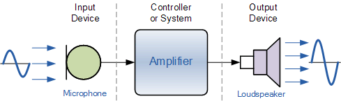
Electrical Transducers are utilized to convert one form of energy into another. For instance, a microphone (input device) converts sound waves into electrical signals for the amplifier to amplify (a process), and a loudspeaker (output device) converts these electrical signals back into sound waves. An example of this type of simple Input/Output (I/O) system is provided below.
Simple Input/Output System using Sound Transducers
There are numerous varieties of sensors and transducers available on the market, and the choice of which one to use depends on the quantity being measured or controlled; the most popular types are shown in the table below.
Common Sensors and Transducers
| Quantity being measured | Input Device(Sensor) | Output Device(Actuator) |
| Light Level | Light Dependent Resistor (LDR)PhotodiodePhoto-transistorSolar Cell | Lights & LampsLED’s & DisplaysFibre Optics |
| Temperature | ThermocoupleThermistorThermostatResistive Temperature Detectors | HeaterFan |
| Force/Pressure | Strain GaugePressure SwitchLoad Cells | Lifts & JacksElectromagnetVibration |
| Position | PotentiometerEncodersReflective/Slotted Opto-switchLVDT | MotorSolenoidPanel Meters |
| Speed | Tacho-generatorReflective/Slotted Opto-couplerDoppler Effect Sensors | AC and DC MotorsStepper MotorBrake |
| Sound | Carbon MicrophonePiezo-electric Crystal | BellBuzzerLoudspeaker |
Input-type transducers or sensors generate a voltage or signal response proportionate to the change in the quantity being measured (the stimulus). The kind or quantity of the output signal is determined by the type of sensor employed. In general, however, all sensor types can be categorized as either Passive Sensors or Active Sensors.
Active and Passive Sensors
- Active Sensor
Active sensors often require an external power supply, also known as an excitation signal, which is used by the sensor to generate an output signal. Active sensors are self-generating devices because their own properties change in response to external action, producing an output voltage of 1 to 10 volts DC or an output current of 4 to 20 milliamperes DC, for example. Additionally, active sensors can create signal amplification.
Active sensor examples include LVDT sensors and strain gauges. Strain gauges are pressure-sensitive resistive bridge networks that are externally biassed (excitation signal) to provide an output voltage proportional to the applied force and/or strain.
- Passive Sensor
A passive sensor, unlike an active sensor, requires no external power source or excitation voltage. A passive sensor, on the other hand, creates an output signal in reaction to an external stimulus. For example, a thermocouple produces its own voltage output when subjected to heat. Then passive sensors are direct sensors that alter their physical qualities, such as resistance, capacitance, or inductance, among others.
Analogue and Digital Sensors
- Analog Sensors
Analog Sensors typically generate a continuous output signal or voltage proportionate to the quantity being measured. Physical quantities such as Temperature, Velocity, Pressure, Displacement, and Strain are all analog quantities because they are often continuous by nature. For instance, the temperature of a liquid can be measured using a thermometer or thermocouple that responds constantly when the liquid is heated or cooled.
Thermocouples used to produce an Analogue Signal
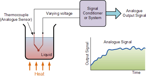
Analog sensors typically generate output signals that vary gradually and continuously over time. These signals typically range in magnitude from a few microvolts (uV) to several millivolts (mV), necessitating some type of amplification.
Consequently, circuits that measure analog signals typically have a slow response and/or poor precision. Using analog-to-digital converters (ADCs), it is also simple to transform analog signals into digital signals for usage in microcontroller systems.
- Digital Sensors
These sensors generate discrete digital output signals or voltages that are digital representations of the quantity being measured, as their name suggests. Digital sensors generate a Binary output signal in the form of a logic “1” or a logic “0” (i.e. “ON” or “OFF”), often known as “ON” or “OFF”. Thus, a digital signal only creates discrete (non-continuous) values that can be outputted as a single “bit” (serial transmission) or by combining the bits to produce a single “byte” output (parallel transmission).
Light Sensor used to produce a Digital Signal

Using a digital LED/Opto-detector sensor, the speed of the rotating shaft is measured in our previous example. The design of the disc that is attached to a spinning shaft (such as from a motor or robot wheels) includes a number of transparent slots. As the disc rotates at the speed of the shaft, each slot passes the sensor and generates an output pulse corresponding to a logic “1” or “0” level.
These pulses are transferred to a register or counter, and then to an output display, which displays the shaft’s speed or rotations. By increasing the number of slots or “windows” in the disc, more output pulses can be generated per shaft rotation. As fractions of a revolution may now be identified, a higher level of resolution and precision is reached. Then, this type of sensor configuration might also be utilized for positional control, with one of the disc slots serving as a reference position.
Compared to analog signals, digital signals or quantities possess extremely high precision and can be measured and “sampled” at a very rapid rate. The digital signal’s precision is proportional to the number of bits utilized to describe the quantity being measured. Using an 8-bit CPU, for instance, will result in an accuracy of 0.390%. (1 part in 256). While the accuracy of a 16-bit processor is 0.0015 percent (1 part in 65,536), or 260 times more exact. This precision can be maintained by manipulating and processing digital quantities millions of times faster than analog signals.
In most circumstances, sensors, and analog sensors, in particular, require an external power source and some type of signal amplification or filtering in order to generate a proper electrical signal that can be measured or utilized. Utilizing Operational Amplifiers, as demonstrated previously, is a great approach to accomplish both amplification and filtering in a single circuit.
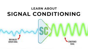
Signal Conditioning of Sensors
As seen in the course on Operational Amplifiers, op-amps can be used to amplify signals in either inverting or non-inverting designs.
The very small analog signal voltages produced by a sensor, such as a few millivolts or even picovolts, can be amplified by a simple op-amp circuit to produce a much larger voltage signal, say 5 volts or 5 milliamps, which can then be used as an input signal to a microprocessor or analog-to-digital system.
In order to provide a useful signal, a sensor’s output signal must be amplified with an amplifier that has a voltage gain of up to 10,000 and a current gain of up to 1,000,000, with the signal amplification being linear and the output signal being an exact reproduction of the input, with the amplitude changed.
Then signal conditioning includes signal amplification. Before the signal can be used, it may be necessary to apply some type of amplification (Gain), impedance matching, isolation between the input and output, or filtering (frequency selection). Operational Amplifiers are useful for doing these tasks.
In addition, when monitoring very slight physical changes, a sensor’s output signal can get “polluted” with extraneous signals or voltages that prevent the required signal from being detected accurately. These undesirable impulses are known as “Noise.” Using signal conditioning or filtering techniques, such as those taught in the Active Filter tutorial, this Noise or Interference can be considerably decreased or even removed.
By employing a Low Pass, High Pass, or Band Pass filter, the “bandwidth” of the noise can be minimized, leaving only the essential output signal. Many forms of inputs like switches, keyboards, or manual controls, for instance, are incapable of a fast-changing state, hence a low-pass filter can be utilized. When interference occurs at a specific frequency, such as the mains frequency, narrow band reject or Notch filters can be utilized to create frequency selective filters.
Conclusion
I hope all of you have understood the basics of Sensors and Transducers. We MATHA ELECTRONICS will be back soon with more informative blogs soon.