
I am text block. Click edit button to change this text. Lorem ipsum dolor sit amet, consectetur adipiscing elit. Ut elit tellus, luctus nec ullamcorper mattis, pulvinar dapibus leo.
-2%Sold out

CD4017 Decade Counter With 10 Decoded Outputs IC
Original price was: ₹22.00.₹12.00Current price is: ₹12.00. inc. GST
CD4033BE CMOS Decade Counter Divider IC
Original price was: ₹75.00.₹65.00Current price is: ₹65.00. inc. GST
AD536 Integrated Circuit RMS-DC Converter IC
Original price was: ₹560.00.₹550.00Current price is: ₹550.00. inc. GST
- Integrated Circuit RMS-DC Converter
- True RMS To DC Conversion
- Laser Trimmed to High Accuracy
- 0.2% Max Error (AD536AK)
- 0.5% Max Error(AD536AJ)
- Wide Response Capability
- Computes RMS of AC and DC Signals
- 450kHz Bandwidth: Vrms>100mV
- 2 MHz Bandwidth: Vrms>1V
- Signal Crest Factor of 7 for 1% error
- DB Output With 60db Range
- Low Power:1.2mA Quiescent Current
- Single or Dual Supply Operation
- Monolithic Integrated Circuit
- -55C-+125C Operation(AD536AS)
Out of stock
Description
The AD536A designed as a complete monolithic integrated circuit that functions as the true RMS-to-dc conversion. It prvide performance that’s comparable or superior thereto of hybrid or modular units costing far more. The AD536A operates by directly computes the truth RMS value of any complex input waveform containing ac and dc components. It crest factor compensation scheme in the device allows measurements with 1% error at crest factors up to 7. Moreover, the wide bandwidth of the device extends the measurement capability to 300 kHz with 3 dB error for signal levels above 100 mV.
The most important feature of the AD536A RMS converters is an auxiliary dB output which not previously available. The logarithm of the RMS output brought bent a separate pin to permit the dB conversion, with a useful dynamic range of 60 dB. Using an externally supplied reference current, the 0 dB level often conveniently set by the user to correspond to any input level from 0.1 to 2 volts rms.
The AD536A designed with laser trimmed at the wafer level for input and output offset, positive and negative waveform symmetry (dc reversal error), and also full-scale accuracy at 7 V rms. As a result, no external trims required to realize the rated accuracy of the unit. There’s full protection for both inputs and outputs. The input circuitry feature take overload voltages well beyond the availability levels. Loss of supply voltage with inputs connected won’t cause unit failure. The output is short-circuit protected. The AD536AK offers a maximum total error of ±2 mV ±0.2% of reading. And therefore the AD536AJ has maximum errors of ±5 mV ±0.5% of reading.
Reviews (0)
Shipping & Delivery

Related products


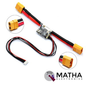
APM/Pixhawk Power Module V6.0 Output BEC 3A XT60 Plug 28V 90A
- Input Voltage Range: 6-28V DC
- Output voltage: 5.3V ± 0.1V
- Maximum output current: 3A
- Maximum current: 90A
- Maximum voltage: 30V
- Supports from 2 cell to 6 cell battery.
- 6P cable can be directly connected to APM/Pixhawk flight control
- Additional 4P rows of pin-free to wire/PIN to connect to another flight control
- Voltage and current measurement configured for 5V ADC.
- Switching regulator outputs 5.3V and 3A max.
- Dimensions: 25mm x 21mm x 9mm
- Weight: 17gm
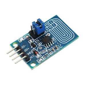
Capacitor Touch Dimmer, Constant Voltage LED Stepless Dimming, PWM Control Board
- Voltage range: 4V to 5V
- Maximum output current: 500mA
- Hole distance: 16 mm
- Aperture: 5 mm
- The lamp brightness can be adjusted by requirement, it is very to operate.
- It can touch in medium protection, such as glass, acrylic, plastic, ceramics, and so on, which is very safe.
- Anti power and phone interference, the EFT can reach above +/-2KV; the touch response sensitivity and reliability will not be affected by the close distance or multi-angle mobile phone interference.
- Dimming mode: Non-polar PWM dimming.
- PCB size: 23 x 20mm

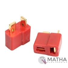
Dean Connector
- Male plug size: About 13* 7* 19mm
- Female plug size: About 13* 7* 15mm
- Current Rating: 30Amps
- Colour: Red and golden
- Material: Plastic and metal
- Provides a secure connection for battery and motor connections
- Eliminates the possibility of wrong polarity connections
- Used in RC hobby, car, boat, plane, helicopter, LIPO battery, etc.
- Dimension: 9x0.7x2cm
- Weight:20gm
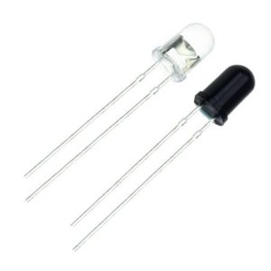
IR LED Sensor
- Size: 5mm LED
- Wavelength: 940nm wavelength (most commonly used)
- Forward current (IF) is 100mA (normal condition) and 300mA (max.)
- 5A of surge forward current
- 24v to 1.4v of forward voltage
- Temperature : -40 to 100 ℃
- Soldering Temperature should not exceed 260 ℃
- Power Dissipation of 150mW at 25℃ (free-air temperature) or below
- Spectral bandwidth of 45nm
- Viewing angle: 30 to 40 degree
- High Reliability
- Excessive radiant intensity
- Having lead spacing of 2.54mm
- Easy to use with breadboard or perf board
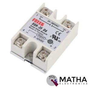
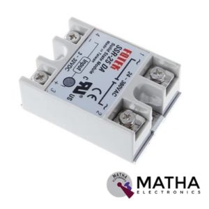
Solid State Relay Module SSR-25DA 25A /250V 3-32V DC Input 24-380VAC Output
- Control mode: DC-AC
- Input voltage: 3-32V DC.
- Output voltage: 24-380V AC.
- Output current: 25A.
- Working voltage: 250V.
- Material: plastic + metal.
- Environment temperature: -30 to +75
- Long service life and high reliability.
- Reduced electromagnetic interference.
- Highly reliable, compact size designed to offer users maximum simplicity.
- Dimension: 6. 5Cm x 4. 5Cm x 2. 2Cm
Reviews
There are no reviews yet.