
I am text block. Click edit button to change this text. Lorem ipsum dolor sit amet, consectetur adipiscing elit. Ut elit tellus, luctus nec ullamcorper mattis, pulvinar dapibus leo.
-17%Sold out

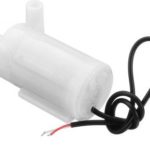
Micro DC 3-6V Submersible Pump Mini water pump
Original price was: ₹180.00.₹150.00Current price is: ₹150.00. inc. GST
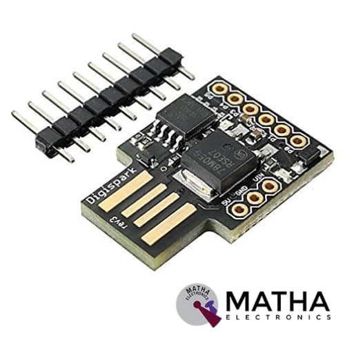
Attiny 85
Original price was: ₹400.00.₹350.00Current price is: ₹350.00. inc. GST
Attiny 5 Version 1
Original price was: ₹300.00.₹250.00Current price is: ₹250.00. inc. GST
- High Performance, Low Power AVR® 8-Bit Microcontroller
- Non-volatile Program and Data Memories
- 8K Bytes of In-System Programmable Program Memory Flash
- Endurance: 10,000 Write/Erase Cycles
- 512 Bytes In-System Programmable EEPROM
- Endurance: 100,000 Write/Erase Cycles
- 512 Bytes Internal SRAM
- Peripheral Features
- High-Frequency PWM Outputs with Separate Output Compare Registers
- USI – Universal Serial Interface (12C, SPI, 1-wire) with Start Condition Detector
- 10-bit ADC
- Single-Ended Channels
- 2 Differential ADC Channel Pairs with Programmable Gain (1x, 20x)
- Speed Grade: 0 – 10 MHz @ 2.7 – 5.5V, 0 – 20 MHz @ 4.5 – 5.5V
- Low Power Consumption
- Active Mode:1 MHz, 1.8V: 300 µA
Out of stock
Description
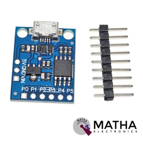
Attiny 5 Version 1 was designed as a low-power CMOS 8-bit microcontroller based on the AVR enhanced RISC architecture. the ATtiny5 achieves throughputs close to 1 MIPS per MHz, by executing powerful instructions in a single clock cycle. This helps the system designer to optimize the device for power consumption versus processing speed. This development board features a 20MHz, AVR 8-bit microcontroller with 8 KB flash, 512 bytes of RAM. It comes with 5 GPIOs, 4 ADCs, 2 PWMs, 1 SPI, and 1 I2C. Moreover, this board is fully compatible with Arduino and it is directly programmed via USB without needing any other programmer. As there is only a total of 6 pins, it is not possible to get everything at the same time. Attiny 5 Version 1 differs from its upgraded version 2, as it is connected using a cable.
This device provides 512/1024 bytes of In-System Programmable Flash, with 32 bytes of SRAM, four general-purpose I/O lines, 16 general purpose working registers, a 16-bit timer/counter with two PWM channels, internal and external interrupts, a programmable watchdog timer with internal oscillator, an internal calibrated oscillator, and four software selectable power saving modes. Moreover, ATtiny5 are also equipped with a four-channel and 8-bit Analog to Digital Converter (ADC). This development board has a wide range of applications in Wearable ring watches, POV Display, Mini Weather Station, Mood Light.
Attiny 5 was manufactured using Atmel’s high-density Non-Volatile Memory (NVM) technology. Moreover, the on-chip, in-system programmable Flash allows the program memory to be re-programmed in-system by a conventional, non-volatile memory programmer. A suite of program and system development tools, including Macro assemblers and evaluation kits, supports this device.
Reviews (0)
Shipping & Delivery

Related products
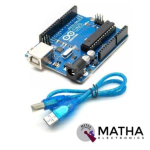

Arduino Duemilanove Development Board with USB Cable
- Microcontroller: ATmega168/ATmega 328
- Operating Voltage: 5V
- Input Voltage: 7-12V
- Input Voltage: 6-20V
- Digital I/O Pins: 14 (of which 6 provide PWM output)
- Analog Input Pins: 6
- DC Current per I/O Pin: 40 mA
- DC Current for 3.3V Pin: 50 mA
- Flash Memory: 16 KB (ATmega168) or 32 KB (ATmega328) of which 2 KB used by the bootloader
- SRAM: 1 KB (ATmega168) or 2 KB (ATmega328)
- EEPROM: 512 bytes (ATmega168) or 1 KB (ATmega328)
- Clock Speed: 16 MHz


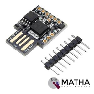
Attiny 85
- High Performance, Low Power AVR® 8-Bit Microcontroller
- Non-volatile Program and Data Memories
- 8K Bytes of In-System Programmable Program Memory Flash
- Endurance: 10,000 Write/Erase Cycles
- 512 Bytes In-System Programmable EEPROM
- Endurance: 100,000 Write/Erase Cycles
- 512 Bytes Internal SRAM
- Peripheral Features
- High-Frequency PWM Outputs with Separate Output Compare Registers
- USI – Universal Serial Interface (12C, SPI, 1-wire) with Start Condition Detector
- 10-bit ADC
- Single-Ended Channels
- 2 Differential ADC Channel Pairs with Programmable Gain (1x, 20x)
- Speed Grade: 0 – 10 MHz @ 2.7 – 5.5V, 0 – 20 MHz @ 4.5 – 5.5V
- Low Power Consumption
- Active Mode:1 MHz, 1.8V: 300 µA

DTMF Shield
- MT8870 Decoder IC.
- 4 Output digital pins.
- Operates on 5V
- Includes MT8870 DTMF Receiver IC
- Receives and Converts Standard DTMF Codes
- Remotely Switch Devices from Anywhere Using the Phone
- Easily Connects to Most Microcontrollers or Roboduino Board
- Low Power Consumption
- 5 On-Board LED's For Data Received Indication
- Standard Header Connections for Control System Connection
- Audio socket for application
- Speaker connector for audio sound checking.
- Microphone connector for over the air remote control system( note, due to environmental noise, without any filtering system this method is not recommended)
- Dimension: 37x37x9mm


ESP8266 WIFI Shield
- Operating voltage 5V (supplied from the Arduino Board)
- Connection via: 802.11b/g networks
- Encryption types: WEP and WPA2 Personal
- Connection with Arduino on SPI port
- on-board micro SD slot
- ICSP headers
- FTDI connection for serial debugging of WiFi shield
- Mini-USB for updating WiFi shield firmware
- 32-bit RISC architecture
- The processor can operate at 80MHz / 160MHz
- 32MB flash memory
- 64kB for instructions
- 96kB for data
- Operates in AP, Station or AP + Station mode
- It has 11 digital pins
- It has 1 analogue pin with 10-bit resolution
- Digital pins except the D0 have interrupts, PWM, I2C and one wire
- Programmable through USB or WiFi (OTA)
- Compatible with Arduino IDE
- Compatible with modules and sensors used in Arduino


HC-05 Bluetooth Shield for Arduino
- Bluetooth serial port Profile
- Bluetooth protocol: Bluetooth Specification v2.0+EDR
- Frequency: 2.4GHz ISM band
- Communication Range: 10M
- Serial Bluetooth module for Arduino
- Can operate in Master, Slave or Master/Slave mode
- UART interface (TTL) with programmable baud rate (SPP firmware installed)
- Default baud rate: 38400(CMD MODE) / 9600(DATA MODE), data bits: 8, stop bit: 1, Parity: No parity
- Onboard PCB antenna
- FCC ID certificated
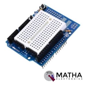
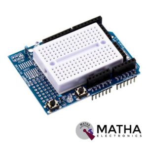
Protosheild For Arduino
- Standard 0.1"x0.1" prototyping grid with big pads
- Comes with Stacking headers and plain header, choose whichever you want when soldering together
- IC pattern for adding DIP ICs up to 20 pins
- Power rails down the middle and sides
- Reset button and an extra general use button
- 2 3mm general use LEDs, red and green, as well as 2 matching resistors
- A pass-thru ICSP stacking header so you can stack any kind of shield on top, and/or use an AVR programmer
- A surface-mount chip area for up to 14 SOIC size parts
- Compatible with tiny breadboards
- Every pin is brought out
- Gold plated pads
- 2 x 0.1uF capacitors on either side for extra power stability
Reviews
There are no reviews yet.