
I am text block. Click edit button to change this text. Lorem ipsum dolor sit amet, consectetur adipiscing elit. Ut elit tellus, luctus nec ullamcorper mattis, pulvinar dapibus leo.
-9%

Generic SIM900 GPRS/GSM Development Extension Board Shield Quad-Band Kit for Arduino
Original price was: ₹1,100.00.₹1,000.00Current price is: ₹1,000.00. inc. GST
- Quad-Band 850 / 900/ 1800 / 1900 MHz – would work on GSM networks in all countries across the world.
- GPRS multi-slot class 10/8
- GPRS mobile station class B
- Compliant to GSM phase 2/2+
- Class 4 (2 W @ 850 / 900 MHz)
- Class 1 (1 W @ 1800 / 1900MHz)
- Control via AT commands – Standard Commands: GSM 07.07 & 07.05 | Enhanced Commands: SIMCOM AT Commands.
- Short Message Service – so that you can send small amounts of data over the network (ASCII or raw hexadecimal).
- Embedded TCP/UDP stack – allows you to upload data to a web server.
- RTC supported.
- Selectable serial port.
- Speaker and Headphone jacks
- Low power consumption – 1.5mA(sleep mode)
- Industrial Temperature Range – -40°C to +85 °C
Description
This Generic SIM900 GPRS/GSM Development Extension Board Shield Quad-Band Kit designed specifically for Arduino and their clones. SIM900 modem designed from SIMCOM. This little GSM/GPRS modem may be incorporated into a wide range of IoT projects. It uses the frequencies 850MHz, 900MHz, 1800MHz, and 1900MHz. The baud rate may be set using the AT command between 1200-115200. It is also appropriate for SMS, voice, and data transfer applications in M2M interfaces with minimal power consumption. This SIM900 is compatible with ARDUINO, RASPBERRY PI, ARM, AVR, PIC, 8051, and other microcontrollers. In addition, it may be directly linked to a computer through Serial Port.
This GPRS Shield is based on SIM900 module from SIMCOM and compatible with Arduino and its clones. The GPRS Shield provides an easier way to communicate using the GSM cell phone network. You may also transmit AT instructions to achieve SMS, MMS, GPRS, and audio through UART (GSM 07.07 ,07.05 and SIMCOM enhanced AT Commands). The shield also includes the SIM900 module’s 12 GPIOs, 2 PWMs, and an ADC (all of which are 2V8 logic).
The SIM900A GSM/GPRS shield Module with RS232 Interface is an all-in-one Quad-band GSM/GPRS solution that can be integrated in client applications. Furthermore, the SIM900 modem’s SIM900 GSM chip and RS232 interface allow for simple connection to a PC or laptop. This is accomplished by connecting the USB to the Serial connection or by connecting the RS232 to TTL converter to the microcontroller. The voltage range of the module is 3.4V to 4.5V.
Application:
- M2M (Machine 2 Machine) Applications.
- Remote control of appliances.
- Remote Weather station or a Wireless Sensor Network.
- Vehicle Tracking System with a GPS module.
Reviews (0)
Shipping & Delivery

Related products
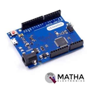

Arduino Leonardo R3
- Board Mode: LEONARDO R3
- Microcontroller: ATmega32u4
- Operating Voltage: 5V
- Input Voltage (Recommended): 7-12V
- Input Voltage (limits): 6-20V
- Digital I/O Pins: 20
- PWM Channels: 7
- Analog Input Channels: 12
- DC Current per I/O Pin: 40 mA
- DC Current for 3.3V Pin: 50 mA
- Flash Memory: 32 KB
- SRAM: 2.5 KB (ATmega32u4)
- EEPROM: 1 KB (ATmega32u4)
- Clock Speed: 16 MHz


ESP8266 WIFI Shield
- Operating voltage 5V (supplied from the Arduino Board)
- Connection via: 802.11b/g networks
- Encryption types: WEP and WPA2 Personal
- Connection with Arduino on SPI port
- on-board micro SD slot
- ICSP headers
- FTDI connection for serial debugging of WiFi shield
- Mini-USB for updating WiFi shield firmware
- 32-bit RISC architecture
- The processor can operate at 80MHz / 160MHz
- 32MB flash memory
- 64kB for instructions
- 96kB for data
- Operates in AP, Station or AP + Station mode
- It has 11 digital pins
- It has 1 analogue pin with 10-bit resolution
- Digital pins except the D0 have interrupts, PWM, I2C and one wire
- Programmable through USB or WiFi (OTA)
- Compatible with Arduino IDE
- Compatible with modules and sensors used in Arduino


L293D Motor Driver Shield
- L293D motor driver chip & 74HC595 shift register
- Four H-bridges
- Terminal blocks and jumper to connect external power, for separate logic/motor supplies
- Up to 4 bi-directional DC motors with individual 8-bit speed selection
- Up to 2 stepper motors (unipolar or bipolar) with single coil, double coil or interleaved stepping.
- 2 connections for 5V ‘hobby’ servos connected to the Arduino’s high-resolution dedicated timer
- 4 H-Bridges: L293D chipset provides 0.6A per bridge (1.2A peak) with thermal shutdown protection, internal kickback protection diodes. Can run motors on 4.5VDC to 25VDC.
- Pull-down resistors keep motors disabled during power-up
- Big terminal block connectors to easily hook up wires (18-26AWG) and power
- Arduino reset button brought up top
- Tested compatible with Arduino Mega 1280 & 2560, Diecimila, Duemilanove, and UNO
- PCB Size: 69 x 53 mm

NUCLEO-64 STM32G071RBT6 Development Board Arduino & ST Morpho Connectivity
- STM32 microcontroller in LQFP64 package
- 1 user LED shared with ARDUINO®
- 1 user and 1 reset push-buttons
- 768 kHz crystal oscillator
- Board connectors: ARDUINO Uno V3 expansion connectors morpho extension pin headers for full access to all STM32 I/Os
- Flexible power-supply options: ST-LINK, USB VBUS, or external sources
- On-board ST-LINK debugger/programmer with USB re-enumeration capability: mass storage, Virtual COM port and debug port
- Comprehensive free software libraries and examples available with the STM32Cube MCU Package
- Support of a wide choice of Integrated Development Environments (IDEs) including IAR Embedded Workbench®, MDK-ARM, and STM32CubeIDE
- Board-specific features
- External SMPS to generate Vcore logic supply
- 24 MHz HSE
- Board connectors: External SMPS experimentation dedicated connector Micro-AB or Mini-AB USB connector for the ST-LINKMIPI® debug connector
- Arm® Mbed Enabled™ compliant
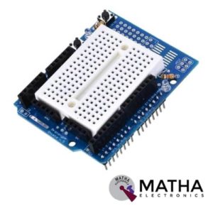
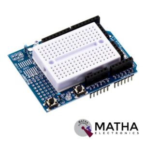
Protosheild For Arduino
- Standard 0.1"x0.1" prototyping grid with big pads
- Comes with Stacking headers and plain header, choose whichever you want when soldering together
- IC pattern for adding DIP ICs up to 20 pins
- Power rails down the middle and sides
- Reset button and an extra general use button
- 2 3mm general use LEDs, red and green, as well as 2 matching resistors
- A pass-thru ICSP stacking header so you can stack any kind of shield on top, and/or use an AVR programmer
- A surface-mount chip area for up to 14 SOIC size parts
- Compatible with tiny breadboards
- Every pin is brought out
- Gold plated pads
- 2 x 0.1uF capacitors on either side for extra power stability
Reviews
There are no reviews yet.